|
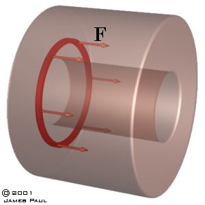
Coil Construction Issues The method of construction used in a coil isn't of much concern if the coilgun is operating under low current densities. However as the current densities rise the electromagnetic forces acting on the turns of the coil become very significant. These forces can be large even without a projectile present. 'Dry firing' a coil will impose a force distribution on the turns which depends on the magnetic flux distribution. The presence of a projectile will modify the distribution and the resulting forces. Take a look at this example of the force which will exist in an energised 'dry' coil. We'll set up a FEMM simulation with a coil measuring 20mm long x 12mm inside diameter x 36mm outside diameter. The current density will be set to 1000Amm-2. Axial Force Simulation - If we create a series of closed integration paths and determine the axial force on this cross section element we can begin to appreciate how the force is distributed throughout the coil.
Fig 1. A small closed path used in this simulation.
The integration path yields the force on a tubular section of the coil as shown in fig 2. The force is axial because the simulation is axis-symmetric.
Fig 2. Simulation yields force on a tubular section of the coil
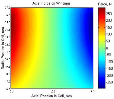
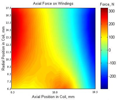
We only need to generate data for one side of the coil since the system is symmetric about its midpoint. It will be a different story when a projectile is introduced. The integration contours form 1mm2 cross sections of the coil so the axial force represents the force per square mm of wire over a revolution. The data from this simulation are plotted as a colour map as shown in fig 3 below (positive force is taken as directed to the right). We'll call this a Type 1 force map.
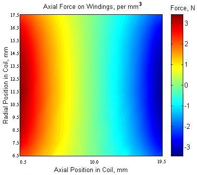
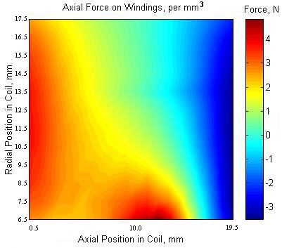
Fig 3. Force distribution on filamentry sections If we want to know the actual force experience by a small section of wire we need to divide the original force values by the circumference of the winding at a given radius. This will result in the force per mm of circumference per square mm of cross sectional area (i.e. roughly per cubic mm). We'll call this a Type 2 force map.
Fig 4. Force distribution on small volume. You should notice that the force distribution now shows the peak force to be occurring around the half thickness of the coil. Notice that the axial force is greatest at the ends of the coil and its direction is towards the centre of the coil. What about the radial force? We'll now look at how the force distribution changes with a projectile halfway into the coil. The Type 1 map is shown below.
Fig 5. Type 1 map with projectile.
Again we can plot the data as a Type 2 map.
Fig 6. Type 2 map with projectile.
Notice how the force is particularly intensive at the centre of the coil, in fact the peak force occurs in a completely different place when the data is viewed in this way. While this type of simulation is interesting it is very labour intensive, it takes about 1-11/2 hrs to generate the full array of data. You may get the impression that there are lots of data points but in fact the data array is only 20x12. The maps are plotted using interpolation between the points to give a smoother look. So what do we make of this? The Type 1 map may have a practical use since it plots the force on a position dependent volume. This may be useful in building a stress model since these models sometimes use distributed loads. The Type 2 map is useful as it gives us an indication of the force on a fixed volume (cubic mm in this case) and lets us see where the peak loading will occur. This is important since this could be the most likely point of mechanical failure. Note that these are force maps, not stress maps. In order to determine the stress distribution we need to use the force values obtained from simulations like those above and apply them to a mechanical stress simulation model. This type of simulation needs additional information about the coil properties as well as which parts are to be considered anchored, i.e. the parts which are fixed. In the case of the coil, one part which could be considered fixed is bottom of the first layer of windings - they are fixed to the accelerator tube. However, if a more accurate analysis is required then we may want to be more realistic and choose the ends of the tube as the fixed parts. This will allow a more accurate analysis of the system since it will take into account the properties and deformation of the tube. It may be possible to directly determine the stress distribution using a high end package such as Ansys which employs coupled field analysis. The stress distribution will probably look very different from the force distribution. As a quick example, consider a vertical solid cylinder. If we look at any small volume we find that the force on that volume is simply its mass multiplied by G with a resulting homogeneous force map. If we now think about the stress we find that the stress gets larger as we move towards the bottom of the cylinder due to the cumulative effect of the weight as we move down the column.
Strengthening the Coil These are a few suggestions on what can be done to strengthen a coil. A more detailed construction methodology requires information on the true stress distributions. It may be possible to determine this to some extent with Quickfield since the programme can perform axis-symmetric simulations for mechanical stress. The simplest thing which can be done is to impregnate the coil with some sort of resin. Many industrial coils use vacuum to assist the penetration of the resin, this isn't really an option for a hobbyist. For minimal hassle the resin can be introduced after the coil has been wound however the penetration is limited and only works well for thin resins. Ideally the resin should be applied after each layer is wound so that it fully permeates the coil. This can be a tedious task since some resins can take many hours to set. Some possible resins which can be used: Acrylic spray - The stuff used to seal circuit boards. This has the advantage of being quite 'runny' and seeps into the windings without much trouble. It's not particularly strong but it does offer good protection against moisture. Epoxy Resin - This comes in a multitude of different varieties. The most suitable types are those with a long setting time. These take several hours to cure and this allows the resin to penetrate the windings more fully. It is possible to thin epoxy with cellulose thinners but you need to make sure that the wire insulation isn't affected by the thinner. The last thing you want is for the finished coil to be ruined by internal short circuits. A faster setting epoxy can be used if it is applied as the coil is wound. This ensures that all the turns are coated but it is a tedious task. For a really strong coil it is necessary to bind the layers with something like glass fibre or carbon fibre reinforcement. The coil then undergoes vacuum impregnation to fill all voids with resin. Based on the simulation above I'd say that simply impregnating the coil with resin is sufficient to strengthen it for most coilgun applications. There is a brief description of high strength coil manufacture at the National High Magnet Field Laboratory. See also Principles of Pulsed Magnet Design for a detailed presentation on the theoretical analysis of stress in pulsed coils. In the next section we'll look at the radial force acting on the windings.
Last Modified: 12 Feb 2004 |