|
Coil Resistance Formula It is quite straightforward
to derive an equation which will give you the coil resistance to an accuracy of
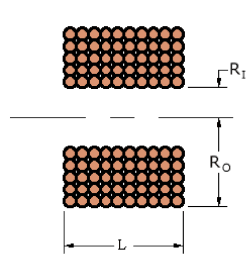
better than +/-10%. This equation uses the main parameters of outer radius, RO,
inner radius, RI, length L and wire diameter
Fig 1 Coil parameters
The
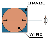
amount of space between adjacent turns will depend on how neatly the coil is wound.
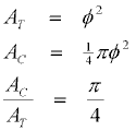
If we consider the wire to be wound neatly so that each strand effectively occupies
a total cross-sectional area of
This
is a reasonable assumption since each layer of the coil lies at a slight helix
angle opposite to the preceding layer so the turns don't fall into the gaps in
the lower layer. However for the general case we will adopt a general ratio, F,
and term it the coil 'filling factor'. I would think that in most instances F
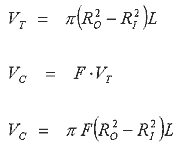
will lie around If we assume this ratio holds throughout the whole volume of the coil we can express the volume of copper wire, Vc, in terms of the total volume, VT, as follows:
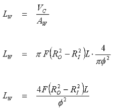
Now that we have an expression for the volume of wire in the coil we can easily determine the actual length of wire, Lw, as follows:
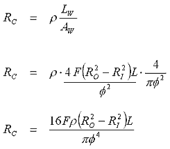
Now that we have an expression for the length of the wire we need one more substitution to express the resistance in terms of the coil parameters. Taking eqn 3 and substituting it into the standard resistance equation gives us the desired result:
So now we have
the coil resistance, RC, expressed in terms of the wire resistivity, If we assume a
filling factor of
Something which
should be noted is that the resistance depends on the Suppose we have two coils, A and B, with the following dimensions, Ro = 20mm, RI =
10mm, L = 20mm, We will use Working out the
resistance of each coil gives - Coil A = 0.41 So you can see that small changes in the wire diameter will have a large effect on the resulting resistance. This formula gives fairly accurate results as shown by the comparison between the measured and calculated test coil resistances. There are several things which can throw the result off; The winding may not be a perfect hollow cylinder -- it might be slightly oval in shape; The wire diameter may not be the exact stated diameter. The resistivity of the wire may not be correctly known - a best guess would be to use the value for pure copper (assuming the wire is copper of course); Finally the windings may not form such a regular pattern and this will alter the ratio of wire volume/total volume (filling factor).
|


