|
Current Sensor Module In
order to measure the current we need some sort of current sensor,
which can simply be just a short section of wire inserted into the
current path. The wire resistance needs to be small compared to
the circuit resistance so that the measurements don't alter the
behaviour of the system. Since many coilgun circuits have resistances
of the order of 1
Here
LW works out as 722 mm using a 1.25 mm diameter wire (resistivity of
copper is 1.7x10e-5
Fig 1. Flat winding
Alternatively, you could wrap the wire so that the turns are wound in alternate directions. This does have quite a lot of inductance compared to other winding configurations so it is best used for low frequencies, if at all.
Fig 2. Opposing winding
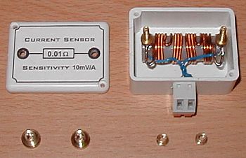
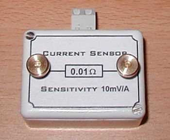
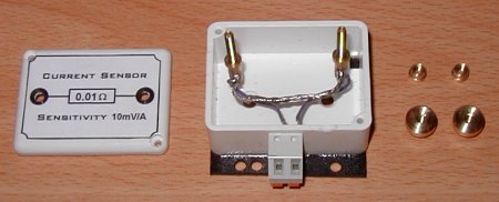
The current sensor module is wound with 1.25mm wire, with the current terminals made from brass. The sensor voltage is brought out to a screw-less terminal block.
Fig 3. Current Sensor Parts
Fig 4. Completed Current Sensor
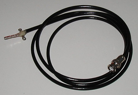
After several attempts at getting the winding length correct the accuracy of the sensitivity is better than +/- 2%. The inductance is less than 1uH. Version 2: I made this sensor using constantan resistance wire so that the wire length and inductance would be minimal.
Fig 5. Constantan element sensor.
The accuracy of the sensitivity is better than +/- 2%. The inductance is primarily internal inductance and so it is irrelevant unless the frequency of the current approaches several hundred MHz. The limiting factor with this sensor is the skin effect which causes more charge to flow close to the outer surface of the wire than in the bulk of the conductor - the resistance is frequency dependant. This sensor consists of several strands of wire to reduce the skin effect but the useful frequency range is still limited to about 400kHz.
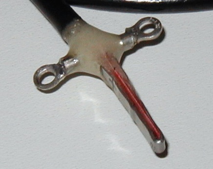
Version 3: This
sensor design is based on a commercially available 0.01
Fig 6.
Fig 7. Sensor element with plastic seperator strip.
|
|