|
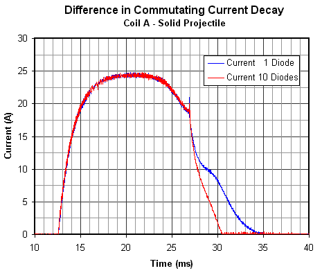
Diode Commutation Results Coil A The graph of fig1 shows the difference in the commutating current decay for 1 diode and 10 diodes.
Fig 1. Difference in commutating current decay.
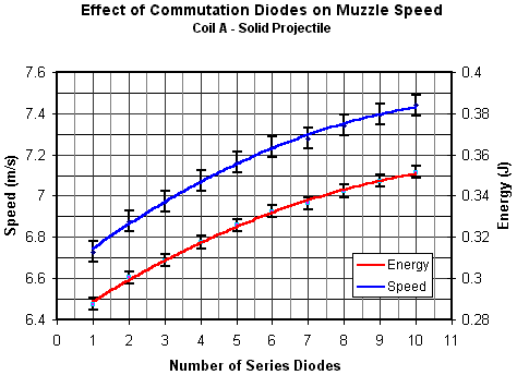
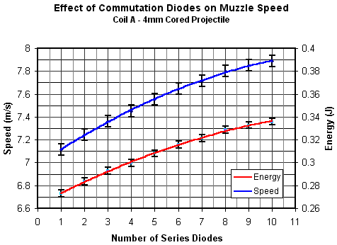
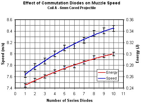
The decay time for 10 diodes is around half that of 1 diode. This should have a pronounced effect on the resulting muzzle speed. The following graphs show the effect of the commutating diode arrangement on the muzzle speed and energy. Five speed measurements were made for each diode arrangement. The data points on the graphs represent the average of the five readings.
Fig 2. Muzzle speed gain using multiple series diodes
Fig 3. Muzzle speed gain using multiple series diodes
Fig 4. Muzzle speed gain using multiple series diodes
Table 1 shows the gain in velocity and energy using 10 diodes instead of 1. Note that the values presented in these tables are the end result of calculations rounded to 3 significant figures.
Table 1. Gains in speed and energy using multiple series diodes.
The limiting factor for the number of diodes is the maximum rated terminal voltage of the switching device. When the device switches off it sees the supply voltage plus the induced 'commutation voltage' so the maximum number of diodes is determined by the difference in the rated voltage and supply voltage divided by the conduction voltage of the diode. For 'large' current pulses through silicon diodes the conduction voltage can be taken as about 1.5V. A more accurate value can be gleaned from the diode's I-V characteristic.
|
|


