|
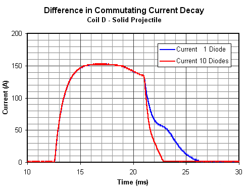
Diode Commutation Results Coil D The graph of fig1 shows the difference in the commutating current decay for 1 diode and 10 diodes.
Fig1. Difference in commutating current decay. Again the decay time for 10 diodes is almost one third that of 1 diode.
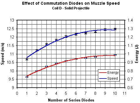
Fig2. Muzzle speed gain using multiple series diodes
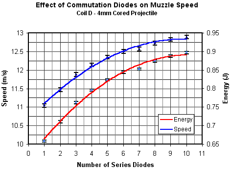
Fig3. Muzzle speed gain using multiple series diodes
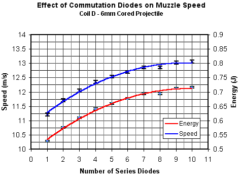
Fig4. Muzzle speed gain using multiple series diodes
Table 1 shows the gain in velocity and energy using 10 diodes instead of 1.
Table 1. Gains in speed and energy using multiple series diodes.
Now in this case we can see that the energy gains are similar to those for coil C with the cored projectiles showing slightly better gains.
|
|


