|
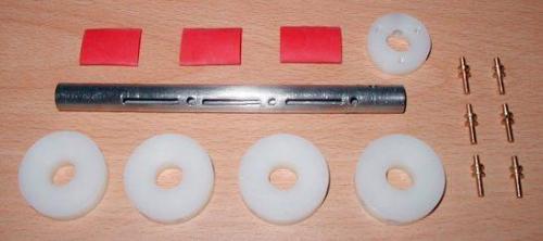
Electromagnetic Pistol: CS-P01A accelerator Construction This is one of the main subsystems so before any framework metal is cut I am going to ensure this component works flawlessly. Fig 1 shows the main mechanical components for the 3-stage accelerator. In this design I decided to use separate holes in the accelerator for the optical gate beam. The reason being that to machine the slot up to this point (thereby allowing beam feedthrough) would only leave a small web between each slot which could result in unacceptable accelerator deformation.
Fig 1. Main components for 3-stage accelerator.
Fig 2 illustrates a trial assembly of the components. It's essential to make sure that everything can be correctly aligned before the parts are permanently fixed.
Fig 2. Components are trial fitted.
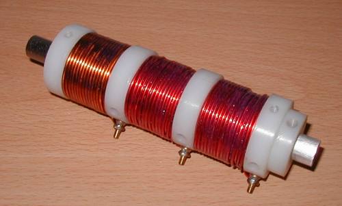
The completed accelerator subsystem is shown in fig 3.
Fig 3. Completed accelerator.
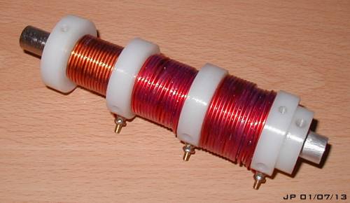
The coils consist of 8 layers of 1.5mm diameter wire impregnated with acrylic lacquer. The wire ends are terminated on brass posts and soldered in place. After looking at the dynamic coil current behaviour, relating it to current density and then comparing magnetic projectile forces in FEMM, I decided that the second and third stages were too thick. They were therefore reduced to 6 and 4 layers respectively. Fig 4 shows the modification.
Fig 4. Modified accelerator with reduced layers.
|