Electromagnetic Pistol: CS-P01A
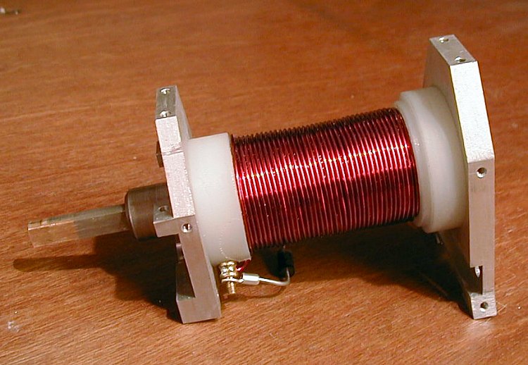
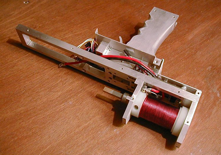
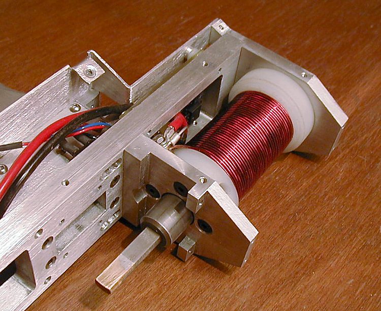
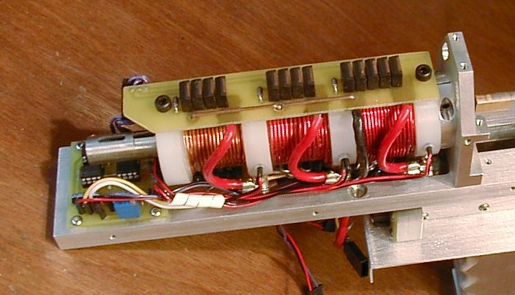
Final Assembly


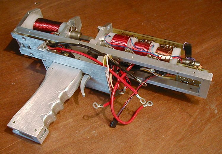
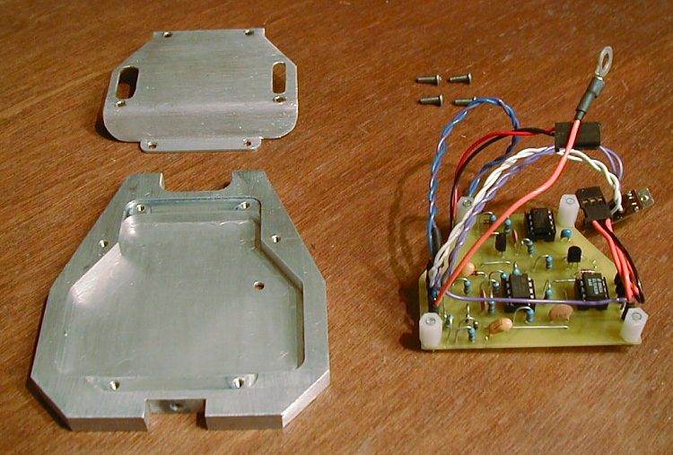
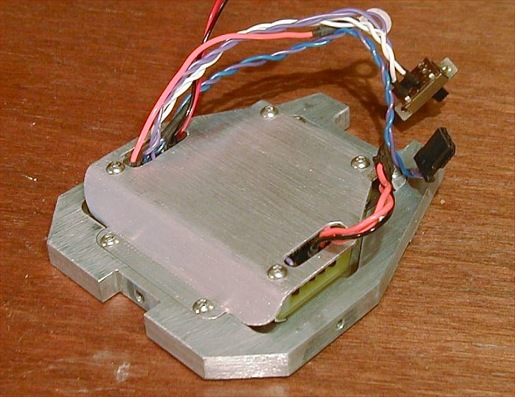
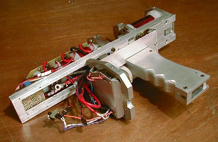
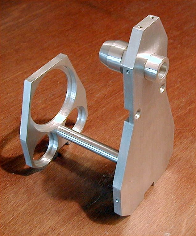
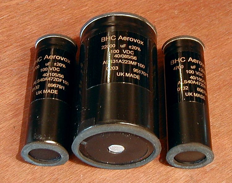
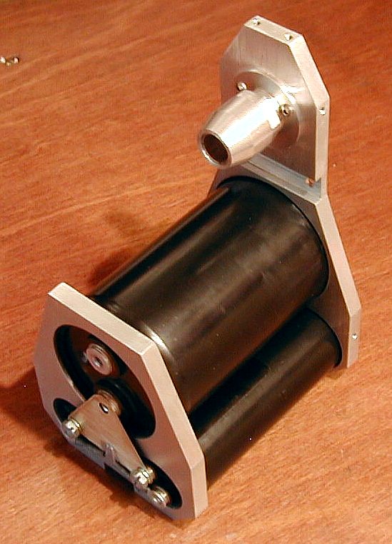
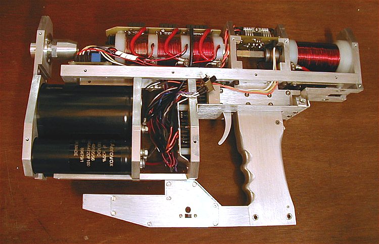
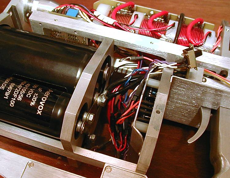
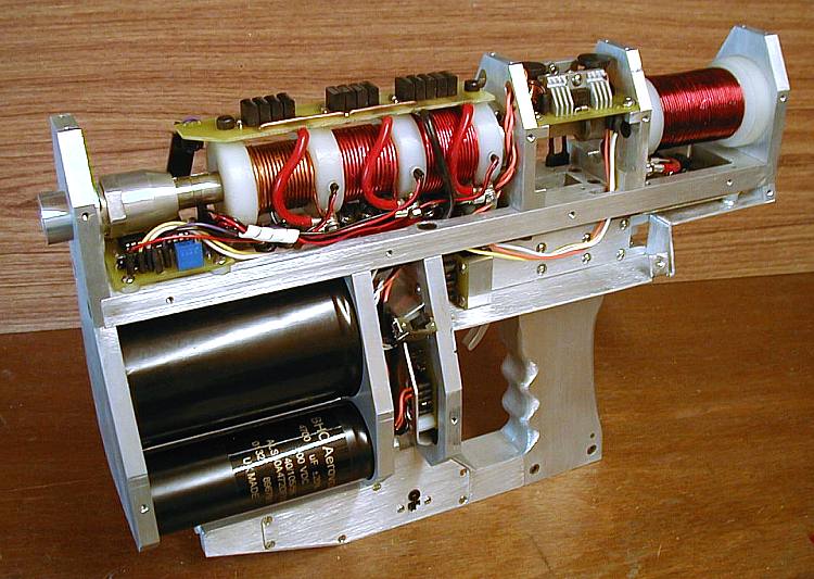
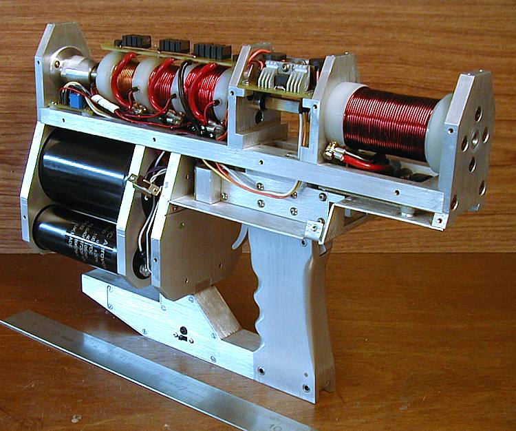
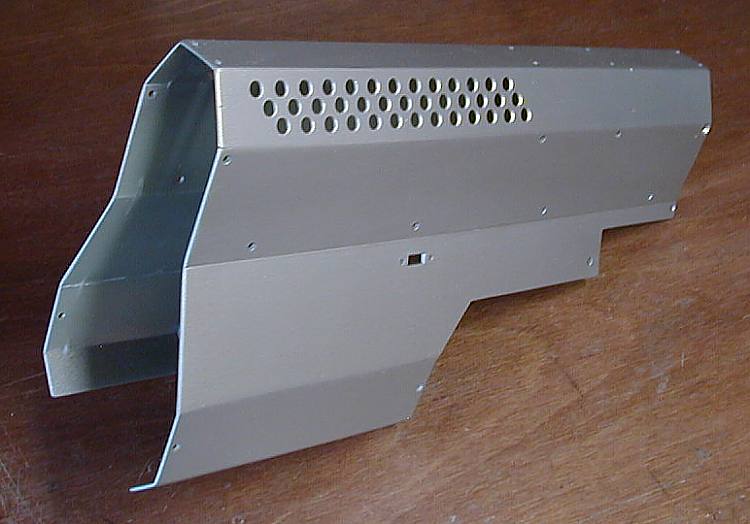
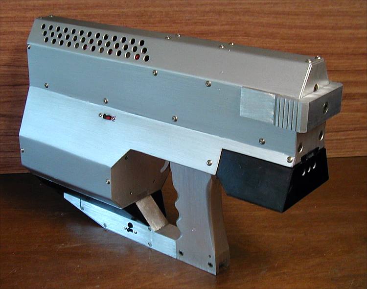
The following images show the general sequence of assembly of the completed coilgun pistol. Click on any image to get a high resolution version (note: files are large ~ 100 k).

Pistol grip halves. Accurate mating alingment is achieved using location pins. Grip assembled. Grip back showing magazine catch housing.
Magazine parts. Fabricated from steel angle section.The spring is polycarbonate. Magazine rear showing catch slot.
Completed magazine.
Projectile loaded into magazine.
Trigger parts. Microcontroller fire control is incorporated into the assembly.
Assembled trigger.
Trigger bridge
Trigger bridge assembled to grip. The rear of the bridge holds the power connector for the cap charging battery pack.
Grip assembled to spine.
Loading solenoid control board installed.
Control board close up.
Rear cover plate. Incorporates apature and guide slot for detatchable battery. Coverplate installed.
Magazine catch parts. The spring is cut from one of many salvaged  VCR parts.
Magazine catch installed. Loading solenoid parts. Loading solenoid asembled. The drawback grip isn't attached at this point.
Loading solenoid installed
Loading solenoid instaled, another view. The brass pile on the end of the bolt prevents the projectile from being strongly attracted to the bolt when magnetised.
Accelerator parts. The accelerator incorporates a 'breach pin solenoid' which holds the projectile in position until the first coil fires.
Optical trigger control board. Output drive is via MOSFET driver chips. Accelerator and optical trigger installed. Accelerator installed, another view.
Charge control board and housing. This system detects the capacitor charge voltage and controls the operation of the boost converter..
Board mounted on bridge. Charge indicator LED protrudes from track side of board.
Charge control assembled into housing.
Charge control assembled onto spine.
Boost converter installed.
Stiffener beam installed.
Control system power supply management. System provides + 5V and +12 V from a 9.6 V NiMH pack,
Control power supply housing fixes to stiffener and grip
Capacitor bay parts incorporating accelerator muzzle clamp.
   
Caoacitor bay trial assembled.
100 V Aerovox electrolytic capacitors. The large cap has had its stud removed. The recesses in the front plate and clamp are  machined slightly oversize to allow the caps to 'float' somewhat on their foam strips.
Capacitor bay assembled. A brass plate  connects the negative terminals together. The smaller caps have bleed resistors connected. The large cap bleeds through the charge voltage sensing divider.
The capacitor bay is slid part way into place to allow for connections to the capacitor terminals.
It's a bit of a squeeze.
The p istol shell is fabricated from glass epoxy laminate sheet sections. The joints are  strengthened with gussets. The finish is 'pearl grey' car body paint.
Completed pistol.


Electromagnetic PistolTop