|
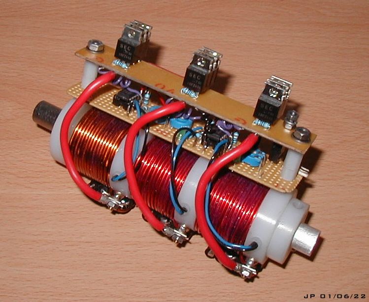
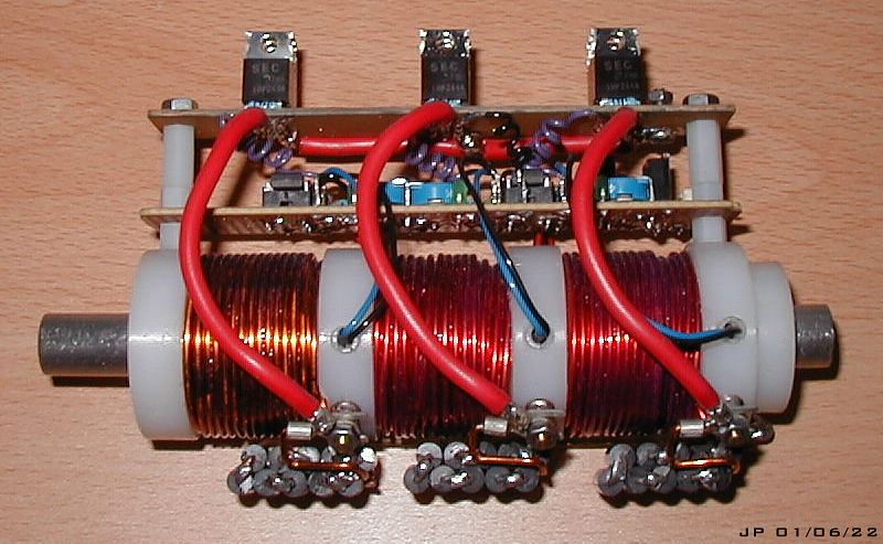
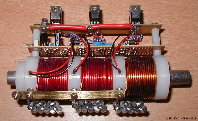
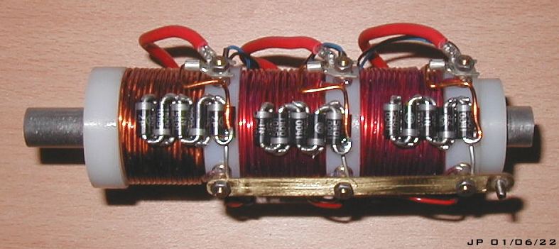
Electromagnetic Pistol: CS-P01A Testing Area - Accelerator Performance (1) Acceleratorl Performance on a 15 cell (~32V) Lead Acid Battery Source - A low voltage optical triggering circuit was constructed for the purpose of investigating some basic multi-coil behaviour. Figs 1-4 show this circuitry mounted on the coilgun accelerator. Click on the images to see a high resolution version.
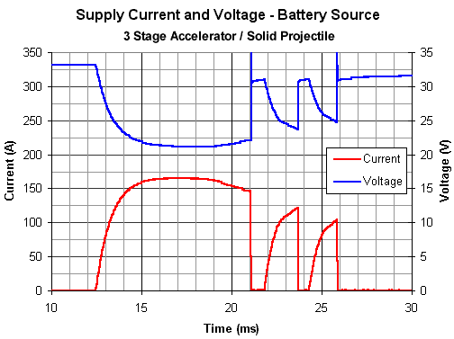
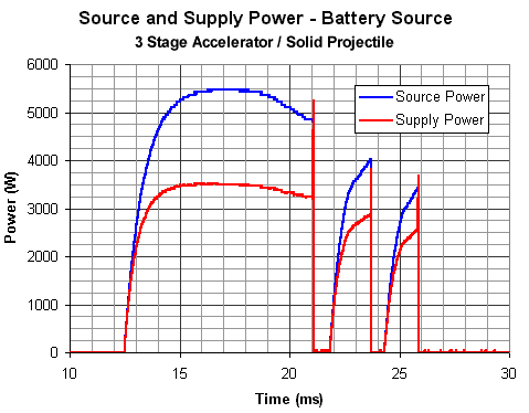
The optical triggering circuit for each coil is virtually identical to that used in the Optical Trigger Module. Each coil is switched by a set of three IRFZ44A mosfets connected in parallel. These mosfets are only rated to 60V so they wont feature in the final capacitor testing. If you have read the details of the commutating experiments then you'll have an idea as to why there are large diode arrays connected across the coils. The gun was originally fired with only a single diode on each coil resulting in a poor muzzle speed of about 13m/s - not much better than a single stage coil! Running with modified diode commutation gives a huge improvement in muzzle speed - the gun now fires at just over 18m/s. Now let's look at the current, voltage and power curves for this accelerator. Fig 5 shows the supply current and voltage, fig 6 illustrates the source and supply power.
Fig 5. Current and voltage traces for 3 stage accelerator.
Fig 6. Power curves showing large internal loss in the source.
The first thing which is striking is the much shorter current pulses in the second and third stages. The 'spikes' in the voltage and supply power curves are due to turn off transients. If we calculate the energy gained by each stage and compare this to the energy lost in each stage then we can determine the efficiencies of each stage. The source energy transfer refers to the total energy generated within the source. Supply energy transfer means the energy which is delivered to the coilgun.
As expected, the efficiency of the first coil is comparable to coil D. This isn't surprising since each coil in this accelerator is dimensionally similar to coil D. What is interesting is that the second and third coils have a much better efficiency rating. The reason for this is that the second and third pulses are much shorter than the first. Also, the current never reaches its maximum steady state value so the peak I2R losses will be less. In this condition the current is said to be induced voltage limited. It's interesting to note the distinct 'knee' in gradient of the leading edges of pulses two and three. This is caused by induced voltage as the projectile penetrates the coil. It would appear that the limiting factor in a multistage accelerator is going to be the rise time of the current. As the projectile accelerates it takes less time to travel into the next coil, so, there comes a point when the frictional and electromagnetic losses equal the limited accelerating force available from the reduced current magnitude, the coilgun has then reached its terminal muzzle velocity. For any given coil configuration the peak current density available in the time window can be increased by using a higher source voltage. The source for the pistol accelerator setup was originally going to be a 50V capacitor on stage one and 80V capacitors on stages two and three. However this was changed after some testing with different capacitor setups.
|