|
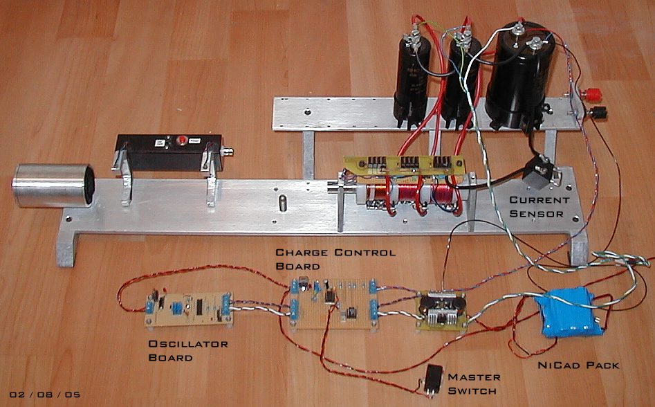
Electromagnetic Pistol: CS-P01A Testing Area - accelerator Performance (2) Accelerator Performance on a capacitor source - In these tests the accelerator was fitted with the pistol prototype MOSFET array consisting of three blocks of four paralleled IRF3415 devices. Fig 1 shows the accelerator setup in the test rig.
Fig 1. Subsystems connected for capacitor test firing.
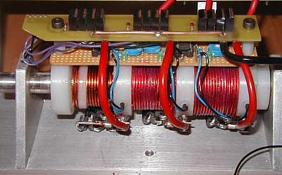
The prototype MOSFET array is shown in fig 2. The tabs of the T0-220 package were cut off due to height restrictions inside the gun. During one of the test firings the projectile jammed in the stage-1 section of the accelerator allowing a larger current pulse than usual - it was enough to blow one of the PCB tracks to the MOSFET block. This component will need a bit of redesign.
Fig 2. MOSFET array.
Fig 3 illustrates
the capacitor current as measured in the 0 V return line. This measurement doesn't
show the commutation current in the coils after the MOSFETS turn off. The current
measuring sensor is a commercial 0.01
Fig 3. Capacitor discharge currents Table 1 gives the data from test firings with a solid projectile using 1, 2 and 3 stages. The 'overall efficiency' column refers to the efficiency of each stage - simply the gain in projectile energy divided by the used energy (the capacitors don't fully discharge so there is some 'residual' energy after firing). Again we can see that the efficiencies of stages 2 and 3 are larger by a factor of about 4 over stage 1. This fact makes it clear that an energy efficient coilgun will be a multistage device. Although the latter stages are much more efficient, they process a significantly smaller amount of energy than stage 1 therefore the total system efficiency is only around 4.7%. The specific distribution of energy in a multistage coilgun is probably quite important in determining the resulting overall efficiency of the gun. This is an aspect of coilgun behaviour that will be investigated for the design of the coilgun rifle.
Table 1. Performance data.
After testing this setup it was decided that the stage-1 MOSFET block needed six paralleled MOSFETS to remain within the device thermal limits under repetitive firing.
|