|
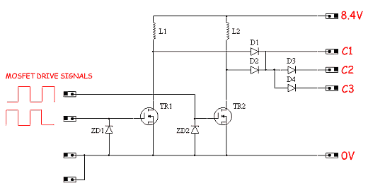
Electromagnetic Pistol: CS-P01A Voltage Converter Design 2 The finalised design of the core converter is shown in fig 5.
Fig 5. Dual converter design.
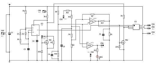
This design uses two converters 'firing' 1800 out of phase with a 50:50 M/S ratio. The operational frequency is 50 kHz. The output diode structure channels current to all three capacitors (they all get charged to almost the same voltage) and ensures that as a capacitor discharges it doesn't get recharged by any of the other capacitors that have yet to be fired. The 50:50 M/S ratio confines the system to operation in 'discontinuous' mode, ie the current in the inductor returns to zero during the delivery phase. The alternate firing sequence places a more even load on the battery pack compared with running the converters in phase (the peak battery current would be roughly doubled). The control system which governs the charging voltage limit is show in fig 6. Fig 6. Charge/Boost control circuit The circuit basically consists of an oscillator, an opamp voltage monitor, and a dual MOSFET driver chip. The oscillator is based on a 7555 chip and produces a 50 kHz pulse train with a 50 % duty cycle. The inverse of this waveform is provided by a MOSFET inverter and both signals are fed into the MOSFET driver. The opamp voltage monitor is based on a dual LM358 chip. One of the opamps provides a 'charged' indication to the microcontroller 'fire control' system. This is also made visible via an LED. The second opamp stops the charging process when the capacitor voltage is a few volts above the desired charged level. Some hysteresis is provided by positive feedback so that the control system doesn't go into high frequency on/off chopping - ie so it doesn't go nuts ;). The charging process can also be enabled/disabled by either a hard switch (connected via CN1) or a voltage level (via CN12). These options allow the charging to be enabled only when a magazine is loaded and when the fire control system is 'happy' with the state of the system.
|


