|
Enhanced Flux Linkage Results and Conclusions
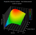
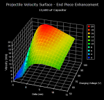
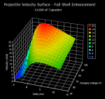
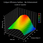
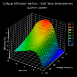
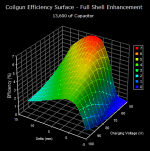
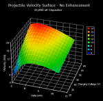
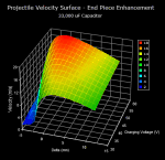
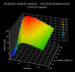
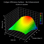
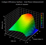
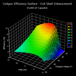
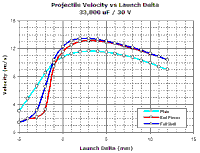
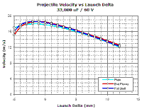
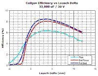
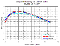
The figures below show the results of experiments 1 through 6. Note the difference in orientation between the axes for velocity and efficiency surfaces.
Effect of flux enhancement on velocity. The graphs in figs 5a and 5b show the velocity curves developed using the 33,000 uF capacitor for charging voltages of 30 V and 60 V respectively. The introduction of flux enhancement makes a significant difference to the peak velocity when the charging voltage is 30 V, but there is very little benefit when the charging voltage is increased to 60 V. The force-displacement curves shown earlier give an indication that there would be proportionally less gain in velocity with a higher charging voltage, although the gain should still be of the order of 20 % (based on the work done). The actual peak velocity using full shell enhancement and a 60 V charge is only a few percent greater than using no enhancement at all. There are several possible reasons for this: the poor filling factor of the shell material creates a distributed air gap which 'leaks' flux and has a reduced permeability compared with solid iron; at higher velocities the magnitude of the suckback impulse might become proportionally larger thereby canceling much of the additional forward impulse - the increased gradient about the midpoint of the force-displacement curve for a flux-enhanced coil suggests that a flux enhanced configuration could be more prone to suckback limitations as the muzzle velocity is increased. We can also see from these figures that flux enhancement can increase the muzzle velocity sensitivity to launch delta in the region around -5 mm to 0 mm. This is expected since the simulated force-displacement curves show that flux enhanced configurations produce a lower projectile force in this region - if the projectile acceleration is reduced at the start of launch then most of the current pulse can decay before the projectile moves into the region of higher force, greatly reducing the muzzle velocity.
Effect of flux enhancement on efficiency. From fig 6a we can see that low voltage peak efficiency is improved by an appreciable amount when flux enhancement is employed. The efficiency gains at a charging voltage of 60 V are minimal. Table 1 shows peak efficiency data for both the 33,000 uF and 13,600 uF capacitors at a charging voltage of 30 V and 50 V respectively.
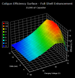
Table 1. Extending the parameter space for the 33,000 uF capacitor with full shell enhancement yields the efficiency surface of figure 7. The efficiency peak at a charging voltage of 15 V is just under 11 %, with the velocity equal to 7.7 m/s.
Conclusions. From the limited study presented here it is clear that flux enhancement can deliver significant improvements in the velocity and efficiency of a single-stage coilgun fired by an optically triggered MOSFET switch. These gains are most evident when the coil current density is low, as would be expected since the copper losses are low and the permeability of the projectile and shell is high. There is little difference between the velocity and efficiency gains offered by end piece and full shell enhancement, so the additional expense and effort involved in making a full shell doesn't seem to be justified, at least in this particular case. Taking account of efficiency limiting factors such as the metallic accelerator tube and low filling factor of the shell material it should be possible to further improve efficiency. The effect of the current turn off point in combination with diode commutation modification is another avenue which can be explored.
Last Modified: 30 Mar 2004 |
|


