|
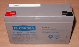
Experimental Energy Sources I'll be using the three common types of energy sources; batteries, capacitors, and inductors. Lead Acid Battery Bank - This consists of five 6V@10Ah sealed lead acid batteries giving a total supply voltage of 30V and a pulsed current capacity of about 200A. Maximum power outputs from this arrangement will be around 5kW (taking into account internal resistance), not exactly very powerful but this is for preliminary testing. In the future I'll be increasing the voltage substantially. A battery source is quite versatile since it can power a coilgun system with any number of coils. The image below shows one of the batteries, the white strip on the top is for tallying up the number of charge cycles the battery has gone through.
Fig 1. 6V@10Ah sealed lead acid battery.
The internal resistance of the five connected batteries can be found by looking at a current drain pulse and the corresponding terminal voltage. Fig 2 shows the internal resistance over a range of current values. The variation of current values is obtained from the exponential growth of the pulse.
Fig 2. Variation of internal resistance with current drain. This is a somewhat
crude method of characterising the battery behaviour. A better way might be to
show the time dependent resistance for specific current drains. In any case it's
sufficient to show that the internal resistance lies somewhere between 60 and
75m Capacitor Bank - Ultimately this will provide energy for all high power testing. I'll probably start off with a 200V system.
Inductor - This will consist of several small mains transformers connected in parallel. The primary winding will be the 'charging' side and needs to be run at a lower voltage than its a.c. rating, this is because it's operating under a d.c. regime during charging.
|
|