|
Finite Element Software The only way to determine the flux distributions and forces in a non-trivial magnetic system to any degree of accuracy is to use a numerical tool such as a finite element package. Two free 2D packages which I know of are Quickfield and FEMM (Finite Element Method Magnetics). In both cases 3D simulations can be conducted if there is rotational symmetry in the problem geometry. This is termed an axisymmetric or axis-symmetric problem and the coilgun fits right in. 'Student' Quickfield is the free version of the commercial package. It has all the functionality of the full Quickfield suit (various other coupled engineering problems can be analysed such as heat generated by current and mechanical stress/strain etc) but it has a limited mesh density. This poses a bit of a problem when trying to determine the forces on parts of the simulated system. The limited mesh density results in quite a rough estimate. Even with its limitation, Student Quickfield is an excellent introduction to a FE package. FEMM is purely a magnetics package but it has no limit on its mesh density so very precise simulations can be run. It feels very much like Quickfield and shares the same stages in problem development. Firstly you need to create a problem geometry. This can be done either directly in the program editor or a geometry can be created in a CAD package and imported as a DXF file. It's fairly easy to create simple geometries in the FEMM editor and you'll not get much simpler than a basic coilgun. Next you need to define the boundary conditions by assigning properties to the areas, edges and nodes of the geometry (nodes aren't usually modified). FEMM comes with a basic set of ferromagnetic materials in a library so you don't necessarily need to generate your own materials, at least to begin with. Once you've applied the boundry conditions you then generate the mesh for the geometry. The default mesh density is quite coarse so it is usually necessary to redefine the mesh density at certain points in the geometry. For example you can specify a mesh density for nodes, edges or areas. Finally hit the analyse button and the solver will churn away for a few seconds (usually) and prompt you with a 'problem solved' message. Now open the results viewer and you can pick off point values of flux density or perform integrations to calculate forces etc. From an interface perspective, the main difference between Quickfield and FEMM is that the problem geometry is orientated vertically in FEMM. Take a look at some of the outputs from these two packages. The problem geometry and boundary conditions are the same in both cases. Click on the images to see a larger version.
Quickfield Outputs -
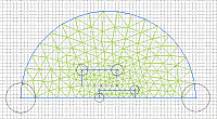
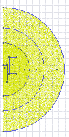
Here we are looking at the model geometry with its meshed areas. The coil is represented by the off-axis rectangular region, the projectile lies on the z-axis and the large semicircular area represents the surrounding air. The circles around the nodes indicate user imposed values on the mesh density. Since Student Quickfield is limited to 200 nodes of mesh it is often a good idea to experiment with mesh density distribution so as to maximise the precision of the simulation.
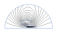
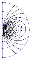
This is a plot of flux lines. The closer the lines are packed together the higher the flux density. The user can specify the density of the lines if necessary although the default value is usually fine.
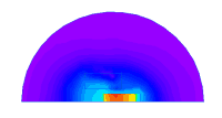
Quickfield can plot many different quantities. This is a colour coded plot of absolute flux density. The plot has a user selectable colour density, this plot originally had 250 colours.You can also plot quantities in primary directions such as radial or axial.
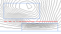
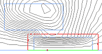
Here we are looking at a contour (red line) over which Quickfield can perform an integration to plot quantities graphically. The contour can be constructed from straight lines and arcs by either free hand drawing using the mouse or you can enter coordinate points into a dialog for greater precision.
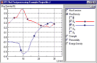
This is an X-Y plot of axial flux density and radial flux density based on the integration contour defined above. Notice that the absolute flux density line is always positive whereas the radial flux density is both positive and negative. It is the radial component of flux which will be dominant in the generation of eddy currents as the projectile moves throught a metallic tube.
To calculate the force on an object you need to place an integration path around it. Quickfield actually gives you the force as a polar quantity (magnitude and angle) and as orthogonal components (radial and axial). Selection of the path can have a significant effect on the resulting force value. It is best to keep the path a short distance away from interfaces such as the air-projectile boundary where there is a rapid change in permeability.
FEMM Outputs -
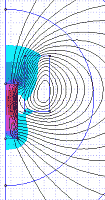
As with Quickfield this image shows the problem geometry and the associated mesh. This model has about 10000 nodes of mesh. The density of the mesh can be controlled by assigning values to nodes, edges or areas. The use of several concentric regions allows a high density mesh to be used around the coil while the areas furthest from the 'core' of the model can be assigned a coarser mesh. This can reduce the solution time by using fewer nodes.
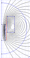
Here we have a flux line plot. Notice that the lines are much smoother than those produced by Quickfield. This is simply due to the greater mesh density.
This is a plot of absolute flux density. FEMM has a limited colour pallet so if there is a large variation in the quantity of interest then the colours on the plot could appear very restricted. (The latest version of FEMM has a more diverse pallet so plots look better)
As with Quickfield, FEMM can perform various types of integration based on user defined contours. The contour line is positioned with the same coordinates as the Quickfield example.
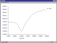
This is a plot of the flux density normal to the integration contour. Since the contour runs parallel with the z-axis this is a plot of radial flux density. Notice the similarity to the lower curve in the Quickfield plot.
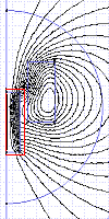
Finally we can place an integration path around an object to determine the magnetostaic force acting on it. FEMM also includes a scripting language (LUA) that can be used to manipulated the model in the preprocessor and perform data exctraction in the postprocessor. This greatly simplifies the task of analysing repetitive problems such as the torque from a motor at various armature positions. Both of these packages are very interesting to use and show how powerful finite element analysis can be. If you intend to use these programs then I'd advise you to read up on electromagnetism since you need some basic knowledge in this area before you can construct a useful model and interpret the results.
Last modified: 12 Feb 2004 |


