|
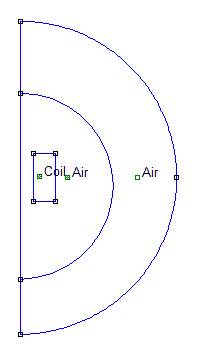
Inductance Calculation Technique This technique is presented in the FEMM manual, and offers a means of determining the inductance of any generalised axisymmetric coil geometry. The first thing to do is to define the coil geometry in the FEMM problem editor. Fig 1 shows a simple rectangular coil whose dimensions are; L_=_27 mm, Ro_=_18 mm, Ri_=_7 mm. The outer boundary of the problem is given a Mixed boundary condition such that the field lines are properly 'formed' when they meet the boundary. This procedure is detailed in the FEMM manual. Materials are also assigned to the relevent regions. Most common materials are available from the FEMM materials library. The 'Coil' material is a renamed copy of the Copper material from the library.
Fig 1. Problem geometry.
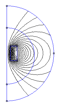
The particular value of the Coil source current density isn't important, but the equivalent wire current value that would produce this needs to be calculated later on. Filling factor values depend on the neatness of the winding as well as on the insulation thickness of the wire. A value of 0.7 is assumed for the filling factor. After setting all the problem parerameters the geometry can be meshed and then solved. The resulting field pattern is shown in fig 2.
Fig 2. FEMM view plot of the field pattern.
In order to determine the self inductance we need to calculate the A.J integral for the coil: Simply select the area selection tool and click on the coil region which should then turn green. Now select the A.J option from the Block Integrals dialog. The resulting A.J value for this coil is 1.009606e-3 Henry Amp2. Now the equation relating the inductance to the coil current is:
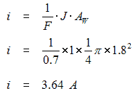
so the last thing we need to know is what i value to use. Going back to the Coil properties dialog we note that the value of J is 1 MA/m2. The diameter of the wire used in the coil is 1.8 mm so the current carried by the wire is:
Therefore the self inductance of the coil is:
We can look at the actual RL response of the coil by applying a step voltage to it via a resistor, and then determine the time constant and hence inductance from the exponential waveform. Another possibility is to discharge a small capacitor into the coil and determine the inductance from the resulting ring down oscillation. In this case the coil, switch, and wiring resistances are ignored, which is valid as long as the damping factor is small (the resistance affects the damping factor which is a variable in the inductance calculation). Table 1 gives the results of the various measurements.
Table 1. Inductance values obtained from different measurements.
Clearly there is a discrepancy between the FEMM-derived value and the measured values, as well as variations within the measured values. This is attributable to the frequency dependent behaviour of the coil - the values are closer to the calculated value when the waveform is slower, be it an exponential or a damped oscillation. If we think of a coilgun current pulse as approximating a half-sine shape, then the equivalent frequency based on very fast pulse duration of 100 us is 5 kHz. It would appear then that the steady state inductance value derived from the FEMM analysis can be taken as a reasonable indication of the coil inductance under coilgun conditions. Uncertainty about the filling factor will affect the accuracy of the FEMM-derived value. For an analysis of the high frequency behaviour of inductors see for example - A. Massarini, M.K. Kasimierczuk, and G. Grandi, "Lumped Parameter Models for Single and Multiple-Layer Inductors"
|


