|
Metallic Tubes The use of a metallic accelerator tube is great in terms of strength but it suffers from a major drawback - induced eddy currents. The problem is not a trivial one, it places severe limitations on the muzzle velocity of the projectile. There are things which can be done to reduce the effect. Firstly we need to try and visualise how these currents exist within the accelerator. If we set up a FEMM simulation and plot the flux distribution along a contour representing a section of accelerator tube as shown below, we can get an idea of the flux distribution. This will allows us to begin to determine how the flux changes as the projectile moves along the accelerator. The simulation is a simple setup with a coil current density of 50MA/m2 (50A/mm2) and a silicon steel projectile.
Here we have the field line plot of the solution to this simulation, the integration contour is situated halfway between the coil and projectile and spans 50mm. Various quantities can be plotted but we are interested in magnetic flux density.
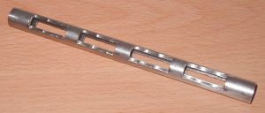
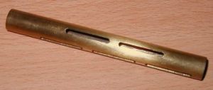
This is a graph of magnetic induction (flux density) normal to the integration path. The normal component is responsible for driving the circumferential eddy currents. This shows that the flux is significant over the length of accelerator tube bounded by the coil and projectile, in this case between 10mm and 40mm. The flux density falls off fairly quickly either side of this boundary. Two examples of slotted accelerators are given below. The stainless steel accelerator had slots cut by machining across the tube, this was done using a milling machine. A file could have been used to achieve the same end but it would take a much longer, particularly on a tougher material like stainless. The brass accelerator slots were again cut with a milling machine, in this case a small diameter mill was plunged into the tube and drawn along it to cut each slot. This is a faster method, especially on a thin tube and a softer metal. On a practical note, there is a lot of work needed after the machining to remove burr from the edges of the slots. A needle file set is invaluable for working in thin slots. Cleanly machined slots are essential for a smooth operation, in fact a projectile can easily get jammed if there are any rough edges left.
This stainless steel accelerator tube is 12.7mm OD with a 1.6mm wall thickness. The projectile must be a good fit in the tube if the slots are wide, otherwise it will attempt to 'fall out' of the slot and ram up against the end of the slot as it moves forward.
I machined this brass tube as a practice exercise, it isn't used for any practical experimentation There are four rows of slots arranged around the circumference, the slots are also offset axially to further reduce eddy current paths. The OD is 12.7mm and the wall thickness is 0.8mm. Brass machines very easily compared to stainless. Note that slotting the tube DOES NOT completely eliminate eddy currents. Consider a tube with a full length slot as shown in fig 5 (ok it's not strictly a tube anymore).
Fig 5. Full length slotted tube.
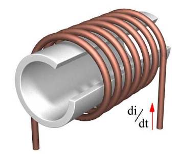
If we pass a time varying current through the coil it will generate a time varying magnetic field. This field (or induction) has an associated electric field that can drive currents in any conductors through which the field penetrates. Since the tube has a finite thickness there remains a closed path around which eddy currents can travel. Fig 6 shows the tube end-on with the current path travelling around the outer surfaces of the tube.
Fig 6. Eddy current path. Although eddy currents can still occur in the tube their magnitude is much smaller because the cross-sectional area of flux enclosed by the tube surfaces is greatly reduced - the electric field associated with the flux through the bore no longer has a closed path around the tube. A theoretical treatment of eddy currents can be found in - Eddy Currents: Theory and Applications, Proceedings of the IEEE, VOL. 80, NO. 10, OCTOBER 1992
|