|
Pulse Trigger Module This module produces a fully variable 12V square pulse over three ranges; 0.1ms - 1ms, 1ms - 10ms, 10ms -100ms. It is designed around the 555 timer and uses a custom delayed negative edge trigger based on a PIC12C509 microcontroller. The microcontroller programming allows a 5s delay between pressing the fire button and triggering the 555 timer. The circuit diagram of fig 1 shows this:
Fig 1. Pulse trigger generator
The module operates by pressing the Prime button (SW1), this illuminates the LED indicating that the 5s countdown has started. At the end of the 5s period the LED is extinguished and the BC108 is pulsed for 10us, generating the negative edge which fires the 555. The on-time of the 555 output is determined by the range selector (SW2) and pulse width dial (VR1). There is a slight overlap in the ranges so that the full range of pulse widths can be generated. The output pulse is 12V and can source about 200mA maximum. The output and circuit ground are brought out to a screw-less terminal block.
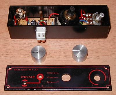
Fig 2. Module parts ready for final assembly
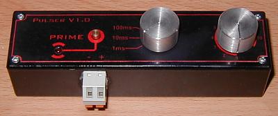
Fig 3. The completed module (the text is easier to read on the real thing)
|
|