|
Open Loop Pulse Triggering Results Coil A First let's look at the current behaviour during a 'dry' firing,
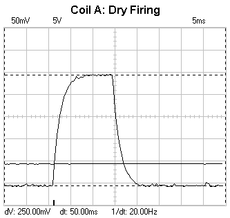
i.e. without a projectile. Fig 1 shows a typical exponential growth with the current
reaching a plateau. On turn off the current decays exponentially with a similar
time constant. Since the current sensor has a sensitivity of 10mVA-1
we can say that the current reaches a maximum of 25A (the horizontal voltage markers
give a dV of 250mV). A simple reality check says this is reasonable - the open
source voltage is about 33V and the coil resistance is 1.35
Fig 1. Coil current during a dry firing
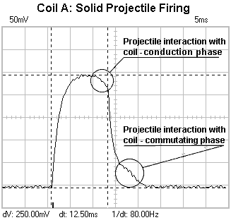
Fig 2 shows how the current curve is modified by the interaction of the projectile and the coil. As the projectile accelerates into the coil it increases the flux linking the coil, this has the effect of inducing a voltage in the coil which opposes the current, the result is that the coil current is driven down a bit as the projectile approaches the middle - we can term this part of the interaction as the 'Conduction Phase'. Let's consider what happens as the projectile begins to leave the coil, the mosfet current is now switched off. As the projectile exits the coil it still carries a magnetisation due to the current which is decaying in the commutating loop, this means that the flux linkage contributed by the projectile is decreasing. If the projectile were stationary the result would be an exponential decay with a slightly longer time constant but the projectiles motion induces additional voltage and creates the little bump in the current decay curve. Note that the voltage induced by the projectiles motion changes from negative to positive as it passes the middle of the coil. Since the energy which drives the extra current comes from the kinetic energy of the projectile, the interaction with the commutating current slows the projectile down a bit. We can term this interaction as the 'Commutating Phase'.
Fig 2. Projectile interaction with coil
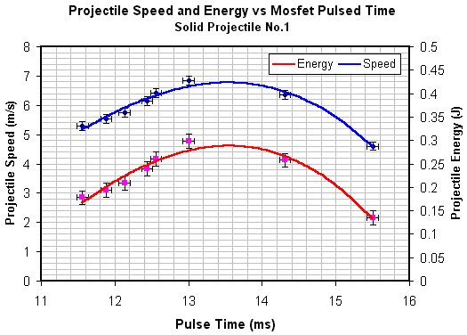
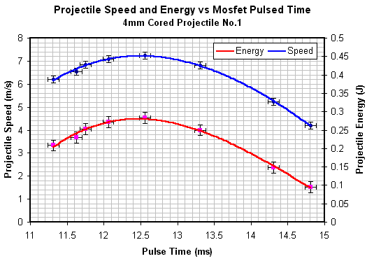
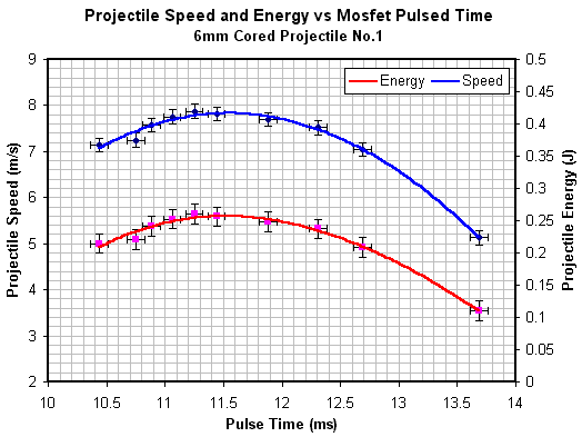
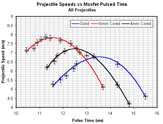
The current pulse length is a little harder to define when the coil is firing a projectile but there is usually a fairly distinct change in current gradient as the mosfet switches off. The time base markers in fig 2 give the pulse width as 12.50ms. It's best to get as much of the curve on the screen as possible in order to maximise the accuracy of the reading - to make the actual measurement in fig 2 I set the time base to 2ms. The graphs below show the data for each of the mild steel projectile types -solid, 4mm cored and 6mm cored. A 3rd order polynomial trend line is fitted to the data points, the error bars are estimated on the uncertainties of the various measuring instruments used. The open loop pulse testing was used to get a 'feel' for the sensitivity of the speed to the pulse length. The graphs in figs 3 - 5 show that pulse timing doesn't need to be 'super critical' to achieve speeds very close to the optimal. While this is true in this instance, we must remember that these are low power tests with slow projectiles. In this case we can allow , say, +/-0.25ms either side of the optimal pulse length without much change in the resulting speed, however, in a high power supersonic coilgun we may need to tighten this to +/-5us or less - a much more critical setup. Finally fig 6 illustrates a comparison between the speeds of the three projectiles.
Fig 3. Solid projectile No.1 speed and energy data
Fig 4. 4mm cored projectile No.1 speed and energy data
Fig 5. 6mm cored projectile No.1 speed and energy data
Fig 6. Projectile Speed Comparison
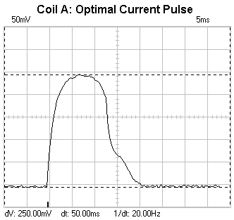
Coil Efficiency Let's look at the efficiency of the coil at the maximum projectile speeds. I'll just concentrate on the coil copper (resistive) losses and ignore the mosfet conduction/switching losses, the commutating diode conduction loss, and power supply losses. These will be investigated in the optical triggering experiments. Fig 7 shows the near optimum current curve for solid projectile No.1.
Fig 7. Optimal current pulse for solid projectile No.1
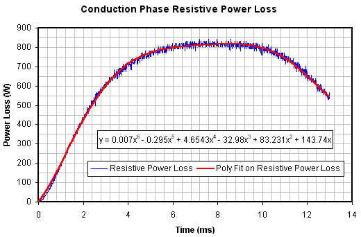
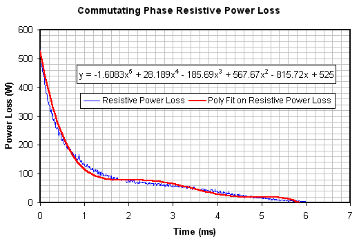
In order to determine the energy lost as heat we need to integrate the power dissipation function over the length of the pulse. The power dissipation function is simply i(t)2R and we can determine the equation by importing the DSO data (text format file) into a spreadsheet package. Fig 8 and 9 show the conduction and commutating phases as separate curves with their own trend lines fitted.
Fig 8. 6th order polynomial trend line fitted to conduction phase
Fig 9. 5th order polynomial trend line fitted to commutating phase
If we integrate the trend line functions over the appropriate time span we can determine the losses. The conduction and commutating phase trend lines yield losses of 8413mJ and 501mJ respectively giving a total loss of 8914mJ. Looking at fig 3 we can see that the peak projectile energy occurs at the 6th data point and has a value of 298(+/-15)mJ, this means that the efficiency of the coil is 3.23(+/-0.17)%. Obviously the efficiency of the whole system will be a bit less than this. In a similar way we can determine the efficiency for the 4mm and 6mm cored projectiles. The data is tabulated below.
Table 1. Energy and efficiency data What can we conclude from all this? It's certainly obvious that the cored projectiles attain a higher speed than the solid projectile, the reason behind this may be due to several effects -
This is all speculation since the system operates under coupled nonlinear interactions making these effects very difficult to analyse in isolation. Note that the efficiencies are quite similar. This is reasonable if you consider that although the cored projectiles carry less energy, they are fired from the coil with a shorter current pulse so the coil losses are also less. On a last point, it's pretty clear that the coilgun is a very inefficient machine, the reason being that the current is primarily limited by the coil resistance. This is much like the early stage of a DC motor spinning up under load after initial switch on. The current will quickly rise according to the time constant of the windings and reach a limit due to resistance. As the motor speeds up the induced voltage in windings reduces the current until the motor reaches its operating speed and current. Electric motors operate in a region where the current is limited primarily by the induced voltage. In this condition most of the energy is transferred to mechanical work and little is wasted in heating the copper. It is quite possible that a multistage coilgun will have improved overall efficiency due to the fact that the projectile will induce an increasing voltage in each successive coil as it accelerates.
|
|


