|
Optical Speed Trap This is by far the most accurate means of measuring the velocity of the projectile. The speed trap consists of two photodiode gates separated by 100mm. The first gate triggers the flip-flop and second resets it producing a TTL level pulse on the BNC connector. It is necessary to reset the circuit when it is first switched on because the flip-flop powers up in a random state. The circuit diagram is shown below.
The gate setup is very sensitive to the IR emitter diode power and the separation of the emitter and detector so it takes a bit of experimentation with resistor values to get it working. This circuit uses the reverse breakdown characteristics of the IR photodiode which allows a low component count however the switching time of the gate is slow (for a photodiode). This limits the useful range of the speed trap to about 50 m/s. In the future an updated version of the speed trap will use the photovoltage signal generated by the diode which has a much faster response.
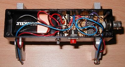
Fig 1. Internal parts of speed trap.
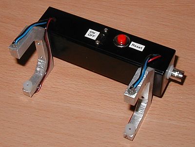
Fig 2. Completed speed trap.
|
|