|
Projectile Design The projectile has as much influence on the performance of a coilgun as any other major subsystem. If we want to design a 'good' projectile then we need to look at reducing or eliminating eddy currents, picking the best material B-H properties, surfacing or skinning the projectile for minimum friction and shape profiling for minimum aerodynamic drag.
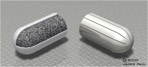
1. Projectile Eddy Currents - If we take a solid ferromagnetic projectile and fire it through a coil then it will experience a highly dynamic magnetic flux. The currents induced by this flux will generate an opposing flux and the net accelerating force on the projectile will be reduced. The penetration of the magnetic field is also limited and so the projectile experiences a reduced bulk magnetisation. The problem becomes more and more significant as the speed increases and the switching times are reduced so if the projectile is intended for a high speed coilgun then steps should be taken to reduce the eddy currents. Two different approaches can be taken, slotting the projectile or powdering it. 2. Slotted Projectile - Slotting the projectile restricts the ability of the eddy currents to flow in the material. The direction of the slotting should be axial since we are more interested in stopping circumferential eddy currents. Obviously slotting will reduce the mechanical strength so progressive depth slotting is a means of reducing this. One possible design is shown below. 3. Powdered Matrix Projectile - An alternative approach is to powder the material and bond it together in a resin matrix. This eliminates eddy currents in all possible directions. The cutaway below shows a bonded matrix projectile with a plastic jacket. This has two advantages, firstly the material can be poured into the jacket like a moulding making fabrication easy and secondly the plastic will readily engage rifling if spin stabilisation is required. One disadvantage of a PMP is that it has to carry the matrix material as baggage which doesn't contribute to the force on the projectile. Bearing this in mind it makes sense to compress the powdered cored material as much as possible so that excess bonding resin is removed.
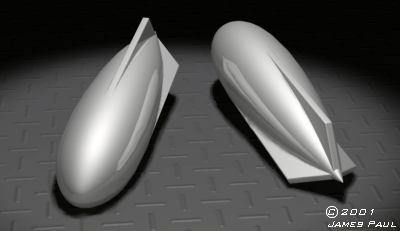
Fig 3.1 Powdered matrix and slotted projectiles 4. Projectile Shape - What effect does the shape of the projectile have on the force curve and the resulting energy transfer? We can answer this by doing a series of FEMM simulations for various projectile shapes starting with a plain rectangular cross-section, then progressing through rounded nose profiles to a sleek profile with a sharp sweeping nose.
5. Aerodynamic Drag - Subsonic Speeds It's quite surprising to realise just how much influence the shape of the projectile can have on its aerodynamic properties. The drag on a projectile can be seperated into two distinc types - form drag and skin friction. Form Drag - Form drag results from the generation of vortices as the projectile displaces the air around it. Fig 5.1 illustrates this.
Fig 5.1 Induced vortices
The formation of vortices requires energy and this comes from the kinetic energy of the projectile. The vortices eventually dissipate behind the projectile and the streamlines return to a smooth profile. In order to minimise the form drag the projectile needs to be 'streamlined'. The best general streamlined shape is shown in fig 5.2.
Fig 5.2 Highly streamlined body
The length/diameter ratio of such a body is termed its 'fineness ratio'. Form drag is minimised when the fineness ration lies between 3 and 4. While this shape might provide minimal form drag it is not a good shape for running down an accelerator tube - it is likely to wobble and possibly jam. Some sort of tail end support could cure this. Fig 5.3 shows fin type supports. These would also provide some flight stabilisation but I'll look at this later.
Fig 5.3 Fin supports guide projectile in accelerator tube.
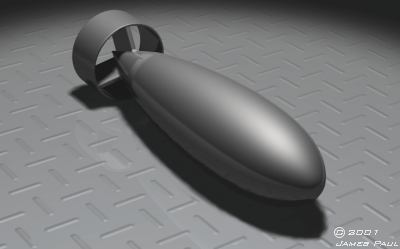
This shape resembles a sort of WW2 drop bomb or a hot air blimp. The addition of fins will increase the form drag somewhat so this design of the projectile would be a compromise between practical functionality and aerodynamic performance. Note that three fins is the minimal number necessary to support the tail end in a plain tube however if the tube is slotted then more fins will be needed to fully support the end in all rotational orientations. Another possibility is to use a tubular 'aerofoil' type fin at the end as illustrated in fig 5.4.
Fig 5.4 Tubular fin arrangement
This type of tail support will be able to run through a tube with any slotting arrangement. Whether this will adversely affect the aerodynamics depends on the shape of the joint area between the fins and the projectile body as well as the shape of the leading and trailing edges of the fins.
|