|
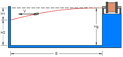
Measuring Speed There are two methods available which lend themselves to a simple experimental set up. 1. Parabolic Method:This method involves firing the projectile at a vertical target some distance, S, from the muzzle of the coilgun. When the projectile is fired at the target it will fall vertically by a distance H1. Using this vertical distance and the horizontal distance travelled we can work out the speed. The diagram below shows the set up.
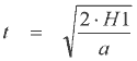
Fig 1.1 Let's derive an expression for the speed V. Assuming V is constant then the time taken for the projectile to reach the target is simply:
Now we can determine the time taken for the projectile to fall vertically by H1 using:
Now the initial vertical speed, u, is zero so we can rearrange to give:
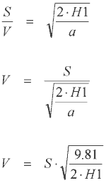
Equating eqn 1.1 and 1.3 gives:
This method requires that the coilgun accelerator tube is set as close to horizontal as possible otherwise the calculated speed value will be off - if the tube is pitched up then the speed will read too high, if it is pitched down then the speed will read too low. The test rig should be set with a spirit level and the corresponding horizontal projection point on the target should be set with either a laser beam or a water level - tube filled with water.
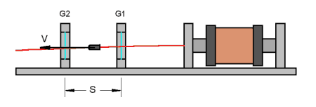
2. Light Gate Method:Here we use a pair of light gates set some distance apart to time the projectile. Using the separation of the gates and the measured flight time we can easily determine the speed.
Fig 2.1
This is a much more accurate method of measurement (probably around 5% error) but it does require some time to build the optical gates and timing system. It is particularly suited to measuring fast projectiles which would otherwise need a long firing range to get a significant H1 drop. It is also less sensitive to the pitch of the accelerator tube. If you intend to use an optical gate system then you will need an instrument which can measure the time between gate triggering events. This can be done using a counter-timer instrument or a DSO. If you are using a counter-timer then you may need to pay attention to the voltage levels of the gates when they are clear or blocked.
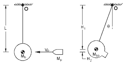
3. Ballistic Pendulum: Conservation of momentum is the basis of this method. The projectile impacts and becomes embedded in the pendulum bob which is free to swing about a pivot. After the impact, the bob swings away and reaches a maximum height which depends on its velocity and hence energy. By relating the momentum and energy considerations we can arrive at a projectile velocity based on the pendulum parameters and swing height. Let's develop an equation for the projectile velocity.
Fig 3.1
All the motion is considered to be occurring about the pivot point, O. The main assumption used is that the dimensions of the bob are small compared to the swing length, L, this allows us to ignore the moment of inertia of the bob about its own mass centre, in other words the bob is being treated as a point mass. We will also assume that the mass of the projectile is very small (<x100) compared to the bob, this means that after the projectile embeds in the bob, the mass centre of the bob remains virtually unchanged. The projectile is also considered to be a point mass. Before the collision - The projectile is travelling at some velocity Vp, and directed exactly at the mass centre of the bob. The bob is stationary. The angular momentum equations for the projectile and the bob are therefore:
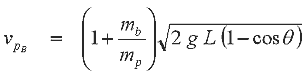
We can equate the momentum before and after the collision as follows:
Now the velocity of the projectile and bob are the same after the collision so:
and therefore we can write:
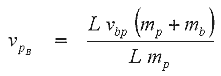
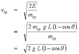
This is the velocity of the projectile before the impact. Now we need to determine the combined velocity after the impact in terms of the swing angle, q. The maximum change in height, H2, of the bob/projectile during its swing gives us the energy of the bob/projectile just after impact. The gravitational potential energy is then:
Now H2 can be expressed as a function of q as follows:
So the gravitational energy in terms of q is:
The kinetic energy of the bob/projectile after impact is:
Rearranging to give the bob/projectile velocity and substituting in the gravitational energy expression:
We can now substitute eqn 3.13 into eqn 3.8 above to give:
If you are intending to use a ballistic pendulum then you need to remember that this equation uses assumptions about the physical layout of the system. You need to keep the swing length long compared to the dimensions of the bob. For example, a bob which is, say, 100mm in diameter needs a swing length of around 1000mm to satisfy the point mass assumption. You also need to pay attention to the swing arm mass, this needs to be light otherwise it will have a significant moment of inertia about the pivot and will skew the results. It's important to realise that the bob mass and swing length need to be large enough to safely absorb the projectile. Suppose we want a pendulum which can handle a 10g projectile at speeds of up to 100m/s. Let's say we want to keep the swing angle below 450 and we intend to use a bob of mass 1kg. First thing we need to do is calculate the projectile/bob energy after the collision, which in this case is 2.5J. We now use this to calculate the height to which the bob will swing. This gives us a value of 0.25m. Since we are looking to keep the maximum swing angle below 450 (for safety considerations), we need a swing length of 0.85m. This is quite large and reflects the substantial energy which a fast projectile carries. You'll need to decide on the best setup for your particular situation. Most low voltage (~50V) single stage coilguns will be lucky to get beyond 25m/s so a smaller pendulum is feasible. There are two possible ways of measuring the swing angle - either attach a pen to the top of swing arm and let it trace the swing on a piece of card, or, attach a potentiometer to the arm pivot and record the voltage output, this can then be related to the angle.
|