|
Three Stage Induced Voltage Triggered Coilgun
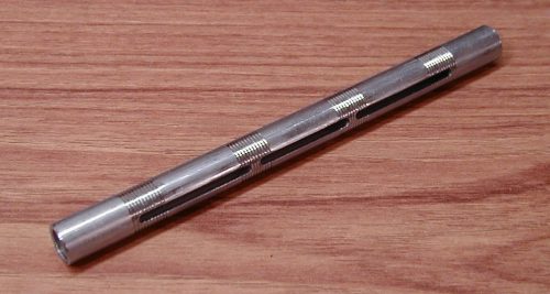
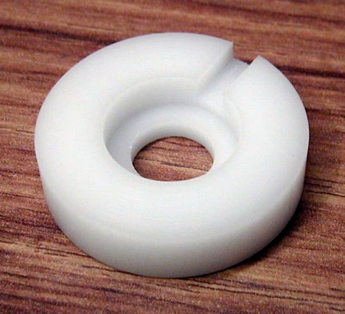
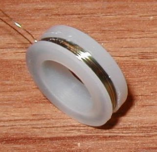
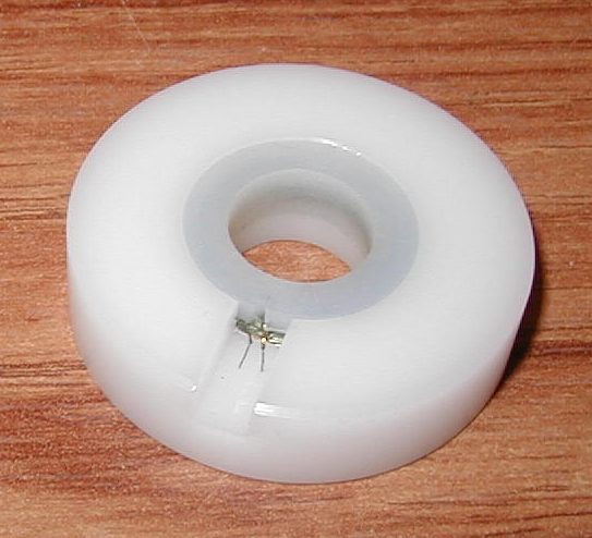
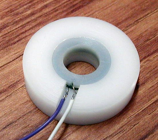
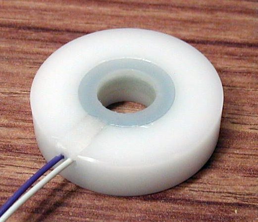
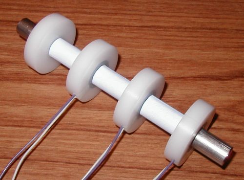
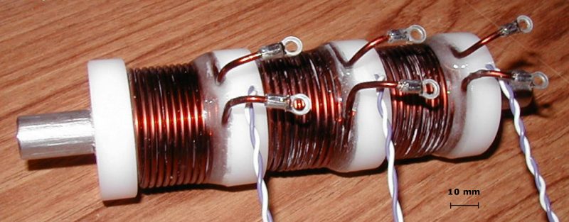
Following on from the development of a single stage induced voltage triggering system, this experiment combines several deta-peak triggers for use in a multistage configuration. The details of the construction of the 3-stage accelerator are illustrated in figs 1a through 1j.
The multistage system operates in a cascading fashion. The sequence is activated by the triggering of stage 1 via a manual switch that sets the delta peak trigger 1 drive signal high. This primes the input to the second stage but does not yet trigger it. Sensor 1 detects the passage of the projectile setting the stage 1 drive signal low. This falling edge triggers the second stage, setting the drive signal high and priming the input to the third stage, and so on. The connectivity of these signal paths is illustrated in figure 2. A disadvantage of this system is that should a triggering event be corrupted in some way the sequence will likely stop. This is in contrast to an optically triggered multistage system where each stage operates independently.
Fig 2. Signal paths required to provide cascading behaviour.
The key timing events are shown in fig 3. The sequence is as follows:
Figure 3. Timing events as seen on the CLK pins and the Q output.
The trigger design for stages 2 and 3 differs only slightly from that used in stage 1. Referring to figure 4 we can see that the drain and source of a small MOSFET are connected across the sensor signal input with the gate of this device being driven by the 'Q-bar' or 'NOT-Q' output of the flip-flop through a signal diode. A small capacitor and resistor are connected in parallel with the gate and source of the MOSFET which creates a delay in turn off when Q-bar goes low. Since Q-bar is high when the stage is idle the sensor voltage is held low until shortly after the stage is triggered. This is necessary in order to prevent the delta-peak trigger from detecting the flux swings from the previous stage.
Fig 4. Multistage configuration for delta peak trigger.
In order for the triggering to follow a cascading pattern each successive stage needs to be triggered by the falling edge of the output trigger pulse from the previous stage. To do this the input trigger signal is inverted via a NOT gate (made from a NAND gate) and then capacitively coupled to the CLK pin of the flip-flop. When the stage is idle the input is low and the output of the NOT gate is high, so there is charge stored in C2. When the trigger input goes high the output of the NOT gate goes low and C2 discharges through R7 thereby priming the input. When the input goes low again the rising edge on the output of the NOT gate produces a pulse on the CLK input of the flip flop, setting the trigger output high. Note
that R2 has been increased in value from 150
Fig 4. Glitch pulse on CLK pin caused by voltage disturbances on the delta peak op amp inputs.
Figure
5a shows an example of the capacitor current for three actively
fired stages. The current is measured by a 10 m
Figure 5a. Capacitor discharge currents.
Figure 5b. Current sensor location.
Some basic velocity and efficiency data for various charging voltages is shown in table 1. It is interesting to note the increase in efficiency of the second and third stages when the higher charging voltage is used. One possible reason for this is that, with the faster projectile velocity, the current peak may more closely coincide with the maximum force position of the projectile as it penetrates the coil. This would naturally result in a more effective transfer of energy to the projectile.
Table 1. 3-Stage coilgun performance data using induced voltage triggering.
Conclusions An induced voltage triggered multistage coilgun can be implemented using a slightly modified version of the single stage delta-peak trigger system. The degree of sensitivity of the delta-peak circuitry can lead to triggering glitches if the circuitry is in close proximity to the drive coils. Adjustments to the sensitivity of the delta-peak trigger can cure the glitch problem, although adequate screening of the circuitry should be an equally valid solution. Last Modified: 16 Jan 2005 |
|
||||||||||||||||||||||||||||||||||||||||||||||||||||||||||||||||||||||||||||||||||||||||