|
Coilgun Basics (2 of 3) TRY IT ! If you're itching to build a coilgun, or simply want to try it with minimal expense, I'll describe a simple nuts and bolts coilgun which can be made from common hobby materials. It is a single stage coilgun with microswitch current timing and runs off a 12V battery. The muzzle energy of this coilgun is less than 0.5 joules.
>> Now you did read the disclaimer, didn't you? <<
As a minimum, you'll need the following tools and basic materials -
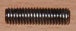
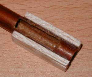
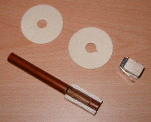
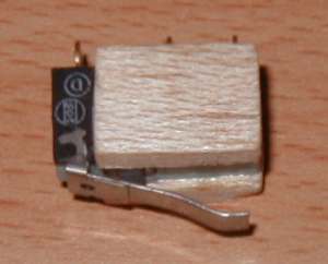
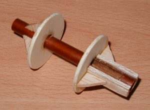
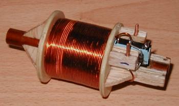
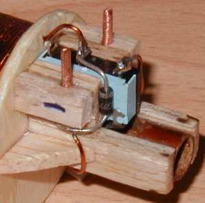
In addition to these you need components for the coilgun parts - First thing you need to decide on is what to use for a projectile and accelerator tube. Ideally the projectile will be a close sliding fit in the tube but a slightly undersized projectile will be ok. Start by finding a suitable tube. The material doesn't really matter for this 'trial' coilgun since it will be very low energy. Any plastic tube and most metal tubes (not steel) will work, so find something about 300mm(12") long with an inside diameter of between, say, 6 and 10mm (1/4"-3/8"). Once you've got your accelerator tube you need to find a suitable projectile. One of the easiest things to use is a steel bolt or a nail. Since they come in a range of diameters and lengths, both imperial and metric, you shouldn't have any difficulty in finding one to suit your tube. Make sure it's not a stainless steel bolt since this metal can be both ferromagnetic and non-ferromagnetic depending on the particular alloy. The length of the bolt isn't that important but I'd suggest keeping the length/diameter ratio between 2 and 5, in other words if the bolt is 10mm in diameter then keep it's length around 20-50mm. Something else you need to think about is that the length of the projectile will determine the length of the coil (or vice versa). The coil length needs to be at least as long as the projectile so a longer projectile will mean a longer coil. Once you've found a suitable bolt, you obviously need to cut off the head and file the edges smooth. There's no point shaping it like a bullet unless you really want to, it won't make any difference with a low energy coilgun. Check that the projectile will slide all the way through the tube without jamming. If it does jam then you'll need to file down the diameter until it slides freely. Don't worry about it getting slightly oval in shape, the most important thing is that it runs through the accelerator without sticking. Next on the agenda is coil wire. Like most other electrical machines, coilguns use enamelled copper wire, also known as magnet wire. This wire has a very thin laquer coating for insulation so that more wire can be packed into a limited space. You could use plain solid core 'bell wire' if you can't find any magnet wire. The wire diameter isn't critical, what is important is that the coil has sufficient resistance to limit the current to a safe level. I'd suggest keeping the current density between 10 and 20Amm2, this will ensure that things won't vaporise if the microswitch sticks in the ON postion. You don't need to worry too much about the rated current of the microswitch, they can easily cope with short current pulses several times their rated value. Most miniature microswitches are rated at 5A, whereas the larger standard switches can handle 15A. Construction The first thing you need to do is cut the microswitch slot. To make a good job of this, you should grip the tube in a vice. Place the projectile inside the section of tube you are gripping so it doesn't get crushed. After you've finished, run a small file around the inside edges of the slot to remove any burr and make sure the projectile still slides through it. You can now cut the balsa strips to shape and glue them in place. Next glue the coil end supports in place, try and get them square with the tube. You may want to stick some gussets to the supports to strengthen the assembly.
Connecting The Battery - You're almost there, all that is needed now is a simple circuit to connect the battery to the coilgun. The circuit below shows the various parts and how they are connected. Loading the projectile closes SW1 so I've included a 'fire button' (SW2) so that the projectile can be loaded with the battery connected. You don't need to worry about holding down the fire button for too short a time since the coilgun will fire the projectile in a fraction of a second.
Does it work? Of course! Download an AVI movie of this coilgun in action. Running on 12V gives a muzzle velocity of 3.5m/s, on 24V this increases to about 5m/s. This is fast enough to be interesting and safe for table top experimentation. If you're looking for a faster coilgun then you'll need to start thinking about higher voltages, semiconductor switches, and optimising the coil geometry. This coilgun is deliberately de-optimised so it isn't dangerous.
|