|
Coilgun Fundamentals 1,2 1. The Coilgun Let's now examine the basic operating principle of the coilgun. A coilgun consists of two interacting parts, the coil and the projectile. Suppose we take something like a short rod of iron or steel and place it next to the coil, what happens?, the rod is attracted into the coil. This attraction occurs because the coil magnetises the rod, effectively creating two separate magnets. The rod is magnetised in the same sense as the coil so the end of the rod which faces the coil 'sees' an opposing pole. Regardless of which end of the coil the rod is placed, it will experience an attraction since the coil will always magnetise the rod in the same sense as its own magnetic field. It would be a different story if the rod was an independent magnet. If this were the case the direction of the current and the orientation of the rod could result in either an attraction or a repulsion. We can look at this in a little more detail by considering the interaction of the flux from the rod and the current in the coil. The diagram below shows a coil and rod in close proximity. The rod is magnetised such that it 'sees' the opposite pole when it faces the coil.
Fig 1.1
It's almost impossible to calculate a value for the attractive force by applying the force equation from the previous page, the complexities involved would likely result in 'ball park values' at best. There would be far too many simplifications required to get an accurate value. What you would need to do is integrate the force value obtained from each elemental part of the coil. This would require some estimation of the flux distribution which isn't possible using analytical maths. This is where we need to turn to numerical field solution programs such as Quickfield or FEMM. These allow us to accurately determine the flux distribution and forces in a static magnetic system. Unfortunately things aren't quite that simple. Solving for a static situation ignores a very important mechanism of electromagnetics, namely induced voltage and current. As the projectile accelerates into the coil, the flux linkage increases generating an induced voltage in the coil which opposes the supply voltage. This tries to reduce the coil current and the magnetic field which, in turn, induces a voltage that tries to maintain the coil current. As you can see, things get a bit complicated. In many instances, the magnetostatic solution may not be a good indicator of the dynamic performance. An exception to this is the situation in which the induced voltage is small compared to the supply voltage, such as a slowly moving projectile. In this instance the current will only be affected slightly. This means that a series of magnetostatic simulations could be used to produce a rough estimation of the muzzle velocity. An example of this comparison can be found in the results section.
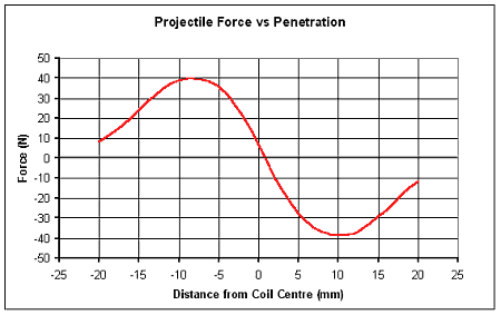
2. Finite Element Force Simulation - In order to get the best out of a coilgun it is necessary to understand how the force varies with the position of the projectile in the coil. The graph below illustrates the typical force variation on a 'rounded nose' projectile measuring 20mm long x 10mm diameter. The force curve is almost symmetrical but the asymmetry of the projectile means that the force drops to zero just beyond the midpoint.
Fig 2.1
The force curve is plotted from a series of 21 simulations with the projectile incremented at evenly spaced intervals, with the coil current density held constant at a conservative 50Amm-2. This is the general form of the force-displacement curve, although there will be variations of the exact shape due to differences between coil and projectile geometries. The force curve generated from a series of magnetostatic simulations is of course a simplification since the induced voltage in the coil will affect the current. The important thing is that it shows quite clearly that the maximum force occurs approximately halfway into or out of the coil. It should also be noted that the force gradient is quite steep as the projectile crosses the midpoint. This suggests that the current pulse should be extinguished promptly, otherwise the projectile will start to be decelerated at a rapidly increasing rate - something which we want to avoid. This type of simulation can be used to give a reasonable estimation of the force curve if the induced voltage is small compared to the supply voltage. Most single stage coilguns should meet this criterion.
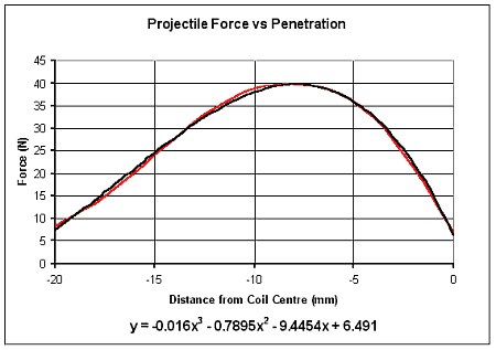
3. Estimating Muzzle Energy and Velocity from a Force Curve - Suppose we have a coilgun system which satisfies the small induced voltage assumption, how do we determine the approximate muzzle energy from the force curve? It's actually quite straight forward, all that is needed is a simple integration. The only tricky part here is deciding what function to use. Since we are only concerned with the left half of the curve (we're turning the current off at the midpoint) let's dump the right hand side and get a curve fit from a spreadsheet programme.
Fig 3.1
A 3rd order polynomial fits this part of the curve very well so integrating this equation gives us
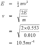
The energy units are in mJ because the distances are expressed in mm. So what does this mean in terms of projectile speed? Firstly we need to know the mass of the projectile, in the simulation above the projectile dimensions give rise to a mass of about 10g so the velocity can be worked out as follows
Clearly this isn't going to create any sonic booms. What you need to appreciate is that very large current densities will be needed to deliver a high velocity projectile from a single stage coilgun. In this example the current was set to 50Amm-2, this is small compared to what is needed for a really fast projectile. Current densities of around 1000Amm-2 will produce 'respectable' velocities.
4. Simple Force Formula - There is a very neat little formula which describes the force on the plunger (projectile) of a solenoid, it goes like this:
where N is the number of turns, I is the current, and df/dx is the rate of change of flux linkage with plunger displacement. N and I are straightforward, but the flux linkage is a quite difficult to determine since it is dependent on the geometry of the coil and the plunger material. Perhaps the best thing to take away from examining this formula is that the force can be increased by either increasing the number of turns, increasing the current, or increasing the change in flux linkage.
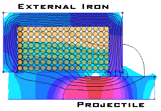
5. Enhanced Flux Linkage - You'll notice from the force equation above that the flux linkage is one of the parameters which affects the force on the projectile. Increasing the flux linkage, for a given coil current, will increase the force on the projectile. The flux linkage can be enhanced by two means; either by using a projectile with a higher saturation flux density (such as iron-cobalt) or by adding external iron to the flux path around the coil.
Fig 5.1
There is a snag of course, the increased flux linkage produces an increased inductance which inceases the time constant of the circuit. The 'cure' for this is to run the system at a higher voltage with an external resistor to achieve similar dynamic and peak current. This is a technique which can be used to improve the performance of stepper motors.
|


