|
Diode Commutation Results Conclusions Why
might this method be used instead of a diode-resistor? If we look at the muzzle
speed obtained using each method then we find that, for a similar overvoltage,
the series diode method yields the best results. Figs 1 and 2 show the voltage
and current data for a 6 segment series diode branch and diode-resistor branch
(R ~ 70m
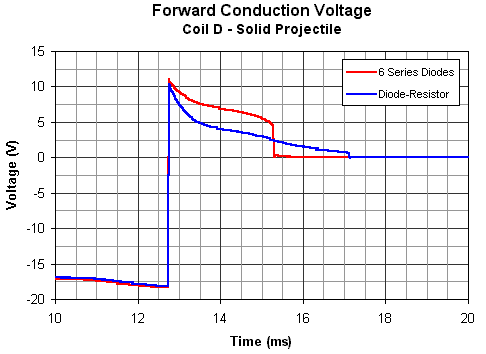
FIg 1. Voltage drop across a series diode and a diode-resistor branch.
Fig 1 shows the commutating branch voltage as the diodes go from reverse blocking to forward conduction, notice that the peak forward voltage for both methods (which gets added to the supply value) is about 10~11V *. There is a slight difference between them but it's not important.
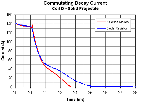
Fig 2. Comparison of current decay using the two methods.
Fig 2 shows that the series diode method is faster at reducing the commutating current and the subsequent retarding impulse. The decay time for the diode-resistor method suffers more from the projectile induced current boost. Table 1 lists the muzzle speeds for the different projectile types resulting from each method. It is interesting to note that the current decay rate is initially similar for both methods but a divergence occurs as the projectile begins to interact with the decaying current.
Table 1. Muzzle speed comparison for commutation methods.
All the projectiles have a slightly greater muzzle speed when running with series diode commutation. The differences are about 5% in terms of speed and around 10% in terms of energy. This is by no measure a huge difference so either method could be used to provide similar gains. Table 2 show an efficiency comparison between a single commutating diode and a series combination of 10 diodes.
Table 2. Efficiency comparison using optical triggering.
Conclusions These results show that a significant amount of kinetic energy is gained by collapsing the current more quickly. Since diodes are cheap this method offers a simple means of improving the performance of closed loop DC current switching. One downside of increasing the overvoltage is that the switching device must be rated to at least the supply voltage plus the initial conduction voltage of the diode array. This may push up the price of the switching device. As always, there is a cost-performance compromise which is hard to crack. Further study is needed at higher voltages in order to establish how this effect is related to the ratio of the supply voltage and the diode array conduction voltage. If the relationship turns out to be anything like proportional then a huge number of diodes would be needed in systems with supply voltages of 100s of volts. This would effectively place an upper limit on the useful range of the 'MultiDiode' method. Also, it is not clear for a given overvoltage whether the MultiDiode method is always better than the diode-resistor method. In fact, if the small performance difference between these methods is a universal feature then it will probably be more cost effective to employ the diode-resistor method even though the resulting muzzle speed is slightly smaller. More detailed experimentation and mathematical modeling is needed to resolve this.
* In both cases the actual voltage rises until the mosfet undergoes avalanche breakdown. This lasts for a few microseconds before the diode(s) begin to conduct sufficient current. The avalanche capacity of the MOSFET allows it to cope with this overvoltage. The 11V value I'm using above is therefore not the true peak value but it represents a peak voltage as seen on a 'millisecond time frame'. This is an important distinction since the MOSFET, under 'coilgun' conditions, can cope with avalanche breakdown for a few tens up to perhaps a hundred or so microseconds.
|
|


