|
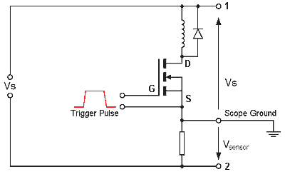
Experimental Measurements Here we will look at how to set up and measure three of the important transient events during a firing sequence. Measuring the supply current and voltage transients makes it possible to accurately determine the total energy supplied to the coilgun. Note that in this the supply voltage means the terminal voltage, we are ignoring the losses inside the voltage source. This lets us concentrate on the efficiency of the coilgun itself without having to complicate the issue with the energy transfer efficiency from the supply. Supply Current and Voltage - The circuit below shows the basic layout for measuring supply current and coilgun supply voltage.
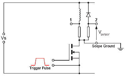
In this circuit we have a resistive sensor in series with the coil and mosfet. We are really interested in the core coilgun (coil and switch) so the supply voltage is measured directly across the coil and mosfet giving us the supply voltage which the coilgun 'sees'. The current sensor resistor is placed in series with the source terminal of the mosfet. This is where all voltages are referenced from. Notice that the current sensor voltage is actually measured the wrong way round, this is easily corrected by inverting the scope channel for this measurement. Another thing to bear in mind is that the trigger pulse is also referenced from the source terminal. You should make the trigger circuit using an isolated supply so it can be referenced from any point in the circuit if desired. If the trigger pulse is referenced from some other point, such as the supply voltage negative terminal, the voltage drop across the wiring between the supply and the mosfet will reduce the trigger pulse voltage as seen by the mosfet (the gate-source voltage). This arrangement allows us to measure two key components, the supply voltage and current. The supply current is the same as the coil current during turn on and conduction but when the mosfet switches off things change. You'll remember from the Switching Devices section that a commutating diode is needed to protect the mosfet from damage due to the transient voltage during turn off. The coil current continues around the diode loop while the current through the mosfet ceases. In order to measure the coil current over the whole firing sequence we need to introduce a current sensor directly in series with the coil. The circuit below shows two possible positions for the sensor, in position 1 the whole firing sequence current can be recorded while in position 2 only the turn off coil current is measured.
Note that the sensor voltage for position 2 needs to be inverted if the scope ground is connected as indicated. Simply inverting the channel will solve this. It is important to be careful how you connect the oscilloscope when making two or more simultaneous measurements. The scope channels will share the same earth so if you connect the earthing clips of the probes to different points in the circuit you are asking for disaster. What you need to remember is when wires carry heavy currents, that is currents well beyond the continuous rated value, they will drop appreciable voltage. That sensor I described above will drop 1V at 100A. If the probes earth clips were connected at either end of this, a potentially damaging current would pass through the scopes earth circuit. At best this will mess up the recorded voltage levels but it could destroy the probes or scope. You are warned! If you really need to measure the voltage across several series component then you could build a simple differential amplifier front end for one of the scopes probes. There are many devices which are suitable for this application, the ***** is one example. Reducing Noise in Signals In the case of current measurements in a coilgun, noise will be introduced by the dynamic magnetic field. This will likely be very small in low energy coilguns but as the current densities rise and the switching times decrease, the amplitude of the induced noise will undoubtedly reach unacceptable levels. The induced noise will be most apparent during the turn on and turn off transients as the magnetic flux undergoes rapid changes. So what can be done to reduce the noise? The first thing to do is to ensure that the sensor is placed as far from the strongest magnetic source as possible, in our case this is the coil. The second thing we can do is use a 'twisted pair' to carry the current sensor voltage signal. This wiring arrangement is simply two wires wrapped around one another which minimises the amount of flux which can affect the signal.
|
|


