|
Inductance Measuring Technique It's possible to measure the self inductance of a circuit using a transient technique. This technique uses the exponential current transient to determine the time constant and hence inductance of the coil. While this method can readily provide inductance information about a circuit it does require the use of a digital storage oscilloscope or graphical multimeter. Some of the more advanced multimeters have an inductance measuring facility but if you are serious about investigating and designing coilguns then a good quality DSO should be a high priority on your shopping list. This article describes how to determine the coil's inductance from a trace of its current transient. In order to accurately
determine the inductance it is necessary to know the circuit resistance
to a reasonable accuracy of say +/- 5%. This is not necessarily
easy since the total circuit resistance is usually around 1 Fig 1 shows the main parameters of this inductive circuit. The transient response to a step voltage is governed by the time constant of the circuit and follows an exponential growth according to the function:
The
time constant
where L and R are the circuit inductance and resistance respectively. An
important feature of this type of exponential growth is that there are almost
exactly 5 time constant periods from the application of the step voltage until
the current stablises. What we are interested in is the period of the time constant.
This is best determined over the initial part of the exponential curve since it
yields a more accurate result. In fact we are only going to consider the very
first time constant period. If we solve the exponential current equation above
for the first time constant period (t /
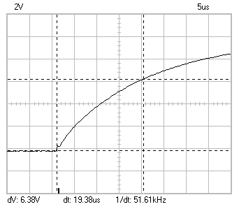
Fig 1
Notice
that the voltage markers (horizontal dotted lines) are set to a
dV of 6.38V which is 63.8% of the applied 10V. This is the closest
value which could be set. The timebase markers (vertical dotted
lines) are set to intersect the transient at the points where the
voltage markers cut the curve. The resulting dt gives us the time
constant for the circuit, in this case it's 19.38us. I typically
work with 3 significant figures unless the calculations or experiments
demand more. So now we have R=100
|


