|
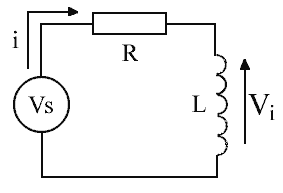
Mathematics 1,2 5. Energy Storage Efficiency in an Inductor The ability of an inductor to store energy allows it to be used for many useful applications, voltage converters being one example. Since real inductors are not ideal, it is useful to know how the energy storage efficiency of an inductor varies as the current builds toward its steady state value. Consider the circuit of fig 5.1. The resistance R represents the total circuit resistance. It can be shown that the current and induced voltage obey exponential functions as given by equations 5.1 and 5.2 respectively. Using these relationships we can determine the efficiency of the inductor energy storage as a function of time.
Fig 5.1. Inductor storage circuit.
The energy stored by the inductor is the time integral of the product of the current and induced voltage. This is described by equation 5.3 -
Performing the integration leads to the relationship of Eqn 5.4.
Initial conditions of i = 0 at t = 0 are used to establish the constant of integration for eqn 5.4. In a similar vein we can develop an equation that describes the energy supplied by the source. This is simply the time integral of the supply power as shown in eqn 5.5.
The integration yields eqn 5.6.
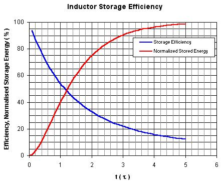
Again the constant of integration is obtained from the initial conditions: i = 0 at t = 0. The efficiency is simply given by dividing eqn 5.4 by 5.6. We can plot the efficiency as shown in fig 5.2.
Fig 5.2. Inductor storage efficiency.
The
behaviour is plotted against time units of It is interesting to note that in order to obtain a high storage efficiency, the ON time of the voltage applied to the inductor must be only a small fraction of a time constant.
|


