|
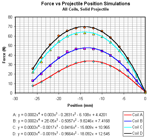
Open Loop Pulse Triggering Results Coil Comparison In this section we'll look at how the coils compare in various ways. The first thing we can consider is how the coils perform compared to simulated results. Fig 1 shows the force-position curves for the four coils using a solid projectile. 4th order polynomial trend lines are fitted to the data points. The equations can be integrated to determine the energy transferred to the projectile, these can then be used to calculate the speeds. Alternatively the data points can be imported into Matlab and numerically integrated.
Fig 1. Force - Position curves for solid projectile
It's important to choose the correct material when running a simulation, the results can vary significantly even with similarly sounding materials. I ran these simulations with 1006 steel which is a low carbon steel and should (I hope) be similar to the mild steel I'm using in its magnetic properties. Table 1 below shows the measured and simulated data.
Table 1. There is clearly a large difference in the simulated and measured data, although they agree better than I expected. Five possibilities come to mind as reasons for these discrepancies:
These are the most obvious factors but there are probably others. I would say that the commutating current interaction is probably the most significant with accelerator tube eddy currents coming second. The rising edge of the current pulse probably isn't that influential because the projectile is going slowly to begin with so the current reaches its maximum before the projectile moves very far. In
the theory section I derived an equation
which can be used to determine the wire diameter which will give the maximum current
density for a given set of coil dimensions and circuit resistance. If we put the
typical test coil dimensions into this equation and specify an RE of
0.08
|
|


