|
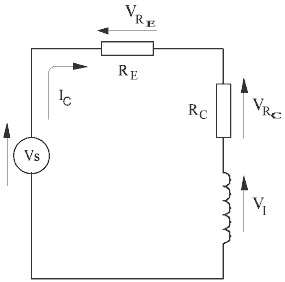
Optimising Current Density It is possible to determine a wire diameter for a given coil geometry which will maximise the current density in the coil. First we need to look at the circuit as shown below -
Fig 1
RE is the external resistance (absolutely everything except the coil), RC is the coil resistance, VI is the induced voltage in the coil and Vs is the source voltage. It is important to include source internal resistance and switching device resistance when calculating RE. We'll keep things managable and concentrate on the steady state condition so we can ignore Vs and VI as variables. First let's define the current density J -
where Ic is the current in the wire and Aw is the wire cross-sectional area. The current density in the coil is then
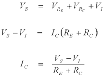
where F is the filling factor. Applying Kirchhoff's voltage law around the loop produces the following relationship -
Static Current Analysis Now if we substitute the coil resistance equation and eqn 3 above into eqn 2 we get -
This is getting a bit messy so I'll lump together some of the constants -
giving us -
This
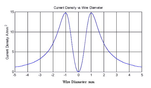
is a fairly simple function and if we plot J against
Fig 2 Obviously
only the +ve values of wire diameter have any meaning. This is quite revealing
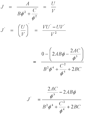
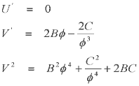
since it shows that there is a certain value of Let's take the final step and tie down an expression which will give the wire diameter for maximum current density without having to plot the whole function. If we differentiate J we can get values for the turning points of the function. Using the Quotient Rule gives us -
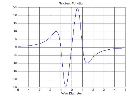
The differentiated function looks like this -
Fig 3
It clearly has three roots and these can be found by equating J' = 0 -
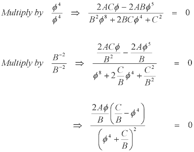
Now apply some math manipulation -
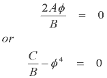
The expression we get above can now give us the roots. The numerator yields two expressions for the roots-
Solving for these -
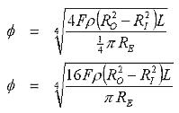
Only the positive root is of interest. Now we can substitute for the constants C and B as defined earlier to give -
The wire diameter given by this expression is a good starting point from which to begin experimentation. Keep in mind that the parameters which you use need to be reasonably accurate for the calculation to give meaningful results. In particular you'll need to produce an accurate value for the RE. Whether you do this by calculation or from measurement is up to you. One crucial aspect missing from this analysis is the induced voltage term. Future analysis will concentrate on developing an expression for optimised current density under dynamic conditions.
|


