|
Electromagnetic Basics In this section we will look at the general electromagnetic principles which are widely employed in engineering. This is a very short introduction to a complex subject. You should find yourself a good book on magnetism and electromagnetism if you want to develop a better understanding in this area. You can also find most of these concepts examined in detail at Fizzics Fizzle. Electromagnetic Fields and Forces Before we look specifically at the case of the coilgun it will be beneficial to briefly examine the fundamentals of electromagnetic fields and forces. Whenever there is charge in motion there is a corresponding magnetic field associated with it. This motion can take the form of current in a wire, orbital electrons in a molecule or the flow of a plasma etc. To help us with our understanding of electromagnetics we employ the concepts of the electromagnetic field and magnetic poles. The differential vector equations which describe this field were developed by James Clark Maxwell.
1. Systems of Units - Just to make life difficult, there are three systems of units in popular use, namely the Sommerfield, Kennely and Gaussian systems. Since each system has different units for many of the quantities things can become confusing. I'll be using the Sommerfield System as outlined below:
Table 1. Sommerfield System of Units
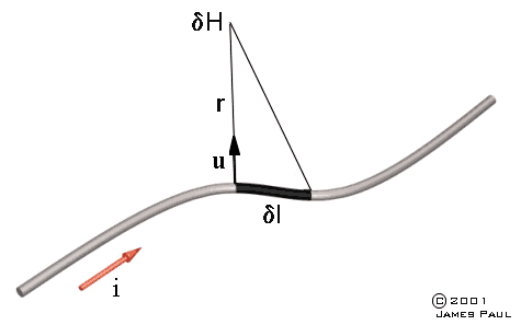
2. Biot-Savart Law - It is possible to determine the magnetic field generated by a current element using the Biot-Savart Law.
Fig 2.1
where
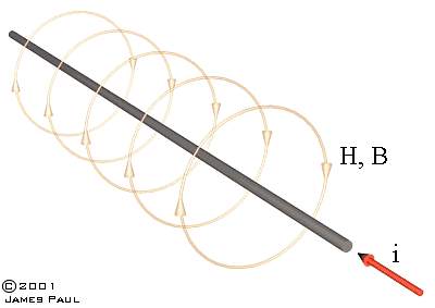
We can determine the magnetic field generated by some basic current configurations using this law. Consider an infinitely long wire carrying a current i. We can use the Biot-Savart Law to derive a general solution for the field at any distance from the wire. I won't repeat the derivation here, any book on electromagnetism will detail this. The general solution is:
Fig 2.2
The field is circular and concentric with the current. Another configuration which has an analytical solution is the axial field of a current loop. While we can develop an analytical solution for the axial field, it's not possible to do this for the field in general. In order to find the field at some arbitrary point we need to solve complex integral equations, this best done with numerical techniques..
3. Ampere's Law - This is an alternative method of determining the magnetic field due to a group of current carrying conductors. The law can be stated as:
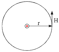
where N is the number of conductors carrying a current i and l is a line vector. The integration must form a closed line around the current. Looking at the infinite wire again we can apply Ampere's Law as follows:
Fig 3.1
We know that the field is circular and concentric with the current so H can be integrated around the current at a distance r to give:
The integration is very straightforward and shows how Ampere's Law can be applied to provide quick solutions in some types of geometry. A knowledge of the field pattern necessary before this Law can be applied.
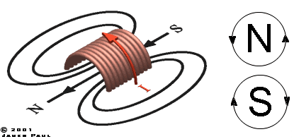
4. Field of a Solenoid When charge flows in a coil, it generates a magnetic field whose direction is given by the right hand convention - Take your right hand and curl your fingers in the direction of the current while extending your thumb, the direction of your thumb now points to the magnetic north end of the coil. The convention for the direction of flux has the flux emerging from a north pole and terminating on a south pole. The field and flux lines form closed loops around the coil. Remember that these lines don't actually exist as such, they simply connect points of equal value. It's a bit like the contours on a map where the lines represent points of equal height. The ground height varies continuously between these contours, in the same way the field and flux from a coil are continuous (the continuum isn't necessarily smooth - a disctete change in permeability will cause field values to change sharply, a bit like a cliff face in the map analogy).
Fig 4.1
If the solenoid is long and thin then the field inside the solenoid can be considered almost uniform.
5. Ferromagnetic Materials Probably the most well known ferromagnetic material is iron but there are other elements such as cobalt and nickel, as well as numerous alloys like silicon steel. Each material has a particular property which makes it suitable for its application. So what do we mean by a ferromagnetic material? Put simply, a ferromagnetic material is attracted by a magnet. While this is correct it's hardly a useful definition and it doesn't tell us why the attraction occurs. The detailed theory of the magnetism of materials is quite a complex subject involving quantum mechanics so we'll stick to a simpler conceptual description. As you know, the flow of charge generates a magnetic field so whenever we find charge in motion we should expect an associated field. In a ferromagnetic material the orbiting electrons are arranged in such a way as to generate a small magnetic field. Now this means that the material is effectively composed of many tiny current loops which have their own magnetic field. Normally the atoms are orientated in small groups called domains, these are directed randomly throughout the material so there is no net magnetic field. However if we apply an external field to the ferromagnetic material from a coil or permanent magnet, the current loops try and align with this field - the domians which are most aligned with the field 'grow' at the expense of the less well aligned domians. When this occurs it results in a net magnetisation and attraction between the material and the magnet/coil.
6. Magnetic Induction and Permeability - The production of a magnetic field has an associated magnetic flux density, also known as magnetic induction. The induction B is linked to the field by the permeability of the medium through which the field penetrates.
where
7. Magnetisation - The magnetisation of a material is a measure of it's magnetic 'strength'. Magnetisation can be inherent in the material, such as in a permanent magnet or it can be generated by external fields sources such as a solenoid. The magnetic induction in a material can be expressed as the vector sum of the magnetisation, M, and the magnetic field, H.
8. Magnetomotive Force (mmf)- This is analogous to electromotive force (emf) and is used in magnetic circuits to determine the flux densities in the various circuit paths. Mmf is measured in ampere-turns or just amperes. The magnetic circuit equivalent of resistance is reluctance which is defined as
where
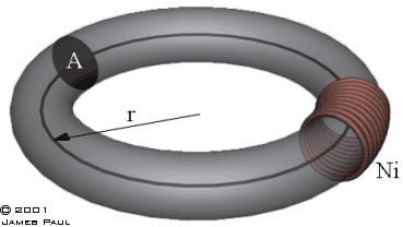
l is the length of the circuit path, Let's look at a simple magnetic circuit:
Fig 8.1
The torus has a mean radius of r and a cross-sectional area A. The mmf is supplied from a coil with N turns carrying a current i. The calculation of reluctance is complicated by the nonlinearity of the materials permeability.
If the reluctance can be determined then we can calculate the flux which exists in the magnetic circuit.
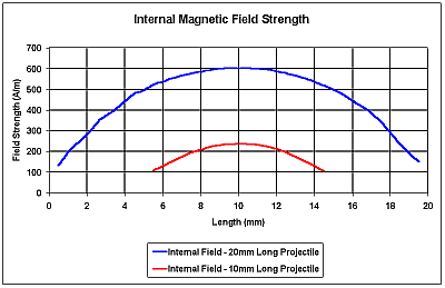
9. Demagnetising Fields - If a piece of ferromagnetic material such as a rod becomes magnetised, poles form at the ends. These poles generate an internal field which tries to demagnetise the material - it acts in the opposite direction to any field which is creating the magnetisation. The result of this is that the net internal field can be much smaller than the external field. The shape of the material has a large effect on this demagnetising field, a long slender rod (high length/diameter ratio) has a small demagnetising field compared to say, a stubby shape like a sphere. From the perspective of coilgun design, this means that projectiles with a small length/diameter ratio require a stronger external field to achieve a given state of magnetisation. Take a look at the graph below, it shows the net internal field along the axis of two projectiles - one 20mm long x 10mm diameter and the other 10mm long x 10mm diameter. For the same external magnetic field there is a large difference in the internal fields, the shorter projectile has a peak field about 40% that of the longer projectile. This would very likely result in a significant difference in the performance of the projectiles.
Fig 9.1
It should be noted that poles only form when there is a discontinuity in the permeability of the material. In a closed magnetic path like a torus, no poles form and so there is no demagnetising field.
Sources:
|
||||||||||||||||||||||||||||||||||||||||||||||||||


