|
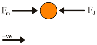
Electromagnetic Basics 14. Electromechanical Energy Conversion - The dynamic response of the motor can be determined by solving the differential equation which governs its behaviour. Fig 14.6 shows the free body diagram of the armature from which we can determine the net force and then write the differential equation.
Fig 14.6 Armature free body diagram
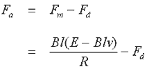
Fm and Fd are the magnetic and drag forces respectively. Since the voltage is a constant we can use eqn 14.1 and the net force, Fa, on the armature is
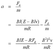
We can now write an expression for the acceleration of the armature
If we write the acceleration and velocity terms as derivatives of displacement, x, wrt time, and rearrange the expression we get the differential equation for the motion of the armature
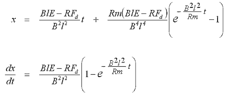
This is a second order nonhomogeneous equation with constant coefficients, and it can be solved by determining the complementary function and the particular integral. The solution method is straight forward (any college level maths text will cover differential equations) so I'll just present the result. One point to note is that this particular solution uses the initial conditions: x = 0, dx/dt = 0.
We
need to assign values to the friction, magnetic induction, and armature mass.
As far as friction is concerned, I'll just use a value of 2N to illustrate how
it affects the motor's dynamic characteristics. Determining a value for the induction,
that will produce a similar accelerating force in the model as it does in the
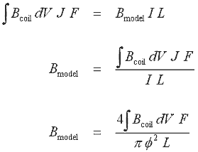
test coils for a given current density, requires that we look at the radial component
of the flux density distribution coming out of a magnetised coilgun projectile
(it's the radial component which develops an axial force). This is integrated
over the volume occupied by the coil and a force expression is generated by multiplying
this by the current density, J, and filling factor, F. The expression is then
equated to BIL for our model and Bmodel is obtained by solving equation
14.15, where
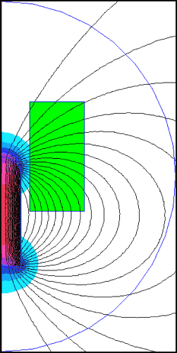
We can look at the magnetic flux from a magnetised projectile (without a coil current) as shown in fig 14.7.
Fig 14.7. Determining volume integral of radial flux density using FEMM
The
projectile is 'magnetised' by giving it a B-H curve and an Hc value in the FEMM
material properties dialog. Values were chosen to resemble strongly magnetised
iron. FEMM gives a value of 6.74x10⁻⁷ Tm3 for the flux density
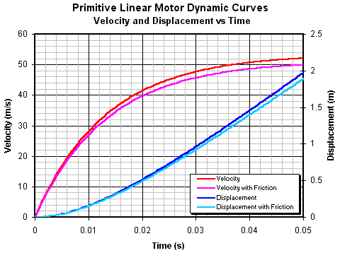
volume integral Bcoil, so using F = We can now plot the displacement and velocity as functions of time as shown in fig 14.8
Fig 14.8. Dynamic behaviour of the linear motor.
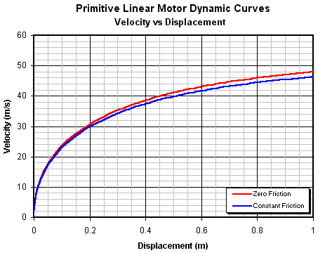
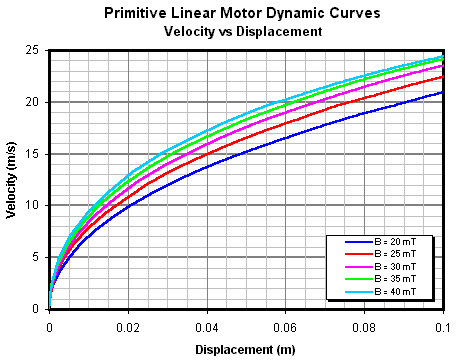
We can also combine the velocity and displacement equations to give a velocity vs displacement function as shown in fig 14.9.
Fig 14.9. Velocity vs displacement characteristics.
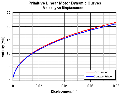
The important thing to notice here is that a relatively long accelerator is needed before the armature begins to reach its maximum speed. This has implications for the maximum efficiency of a practical accelerator. If we zoom in on the curves we can see what velocity is achieved over a length equal to the length of the active material in the coilgun pistol accelerator coils (78 mm total).
Fig 14.10. Close up of velocity vs displacement curves.
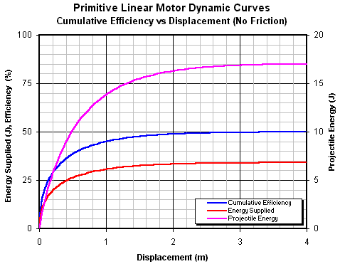
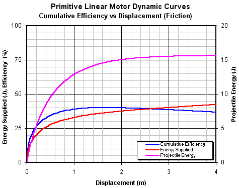
This is surprisingly close to the actual performance of the three stage pistol accelerator, however, this is just a coincidence since there are several significant differences between this model and an actual coilgun - eg in the coilgun the force is a function of the velocity and displacement coordinates whereas, in the present model, the force is only a function of the velocity coordinate. Fig 14.11 is a plot of the cumulative efficiency of the motor as the projectile accelerates.
Fig 14.11. Cumulative efficiency as a function of displacement with no friction losses.
Fig 14.11. Cumulative efficiency as a function of displacement with constant friction losses.
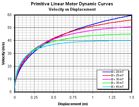
The cumulative efficiency illustrates a fundamental property of this type of electrical machine model - the energy gained by the armature when it accelerates from rest up to its no-load speed is exactly half the total energy supplied to the machine. In other words, the maximum possible efficiency of an ideal (frictionless) accelerator fired by a step voltage is 50%. If friction is present then the cumulative efficiency exhibits a maxima turning point caused by the machine doing work against the friction. Finally, let's look at the effect of B on the velocity-displacement dynamics as shown in figs 14.10 and 14.11.
Fig 14.11. Effect of B on velocity-displacement gradient.
Fig 14.12. Small displacement region where increasing induction yields a greater velocity.
These curve sets show an interesting property of this model in which a larger field induction initially yields a higher velocity over a given displacement, but as the velocity increases the lower induction curves 'overtake' those representing stronger induction. This makes sense when you consider that the stronger induction will yield a greater initial acceleration, however, the correspondingly larger induced voltage causes the acceleration to decrease more rapidly allowing the lower induction curves to 'catch up'.
So, what can we learn from this model? I think the important thing to realise is that, starting from standstill, the efficiency of such a motor is going to be quite low, especially if the motor is short. The instantaneous efficiency increases as the projectile gains speed due to the induced voltage reducing the current. This increases the efficiency because the resistive power loss is dropping while the mechanical power is increasing (see figs 14.3, 14.4), however, since the acceleration is also dropping it takes progressively more displacement to make use of the improving efficiency. In short, a linear motor subjected to a step voltage 'forcing function' is going to be quite an inefficient machine unless it is very long. This model of a primitive motor is instructive in that it points to the cause of the typically poor efficiency of coilguns - namely a low motion-induced voltage. The model is oversimplified as it takes no account of the nonlinearities and inductance elements of a practical system, so to refine the model we need to incorporate these elements into our electrical circuit model. The next section will develop a generalised differential equation for a single stage coilgun. The analysis will attempt to derive an equation which can be solved analytically (some simplification will be needed), failing that, I'll need to use a Runge Kutta numerical integration algorithm.
Sources:
|


