|
Electromagnetic Basics 10. Force on Charged Particle - So how do we calculate forces on current carrying conductors? Lets start by looking at the force on a charge moving in a magnetic field. I'll adopt the general approach in 3 dimensions.
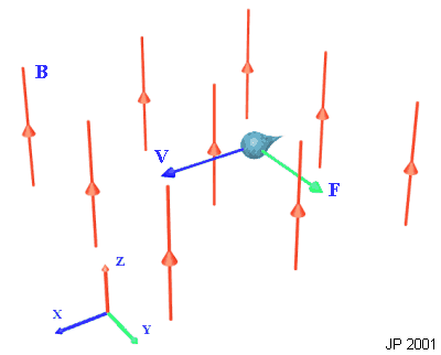
This force is determined by the vector cross product between the charges velocity, v, the magnetic induction, B, and is proportional to the value of the charge. Consider a charge, q = -1.6x10⁻¹⁹ C, moving at 500m/s in a magnetic field of induction 0.1T, as shown below.
Fig 10.1. Charge in motion experiences a force
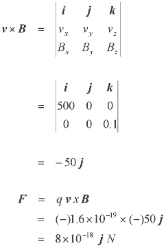
The force experienced can be easily calculated as follows: The velocity vector is 500 i m/s and the induction is 0.1 k T so:
Obviously if there is nothing resisting this force then the particle will be deflected (it would describe a circle in the x-y plane for the case above). There are plenty of interesting things which can be achieved with free charged particles and magnetic fields - you're reading this on one of them. 11. Force on Current Carrying Conductor Let's now relate this to the force experienced on a current carrying conductor. There are a couple of different ways of deriving the relationship. We can describe the conventional current as the rate of flow of charge -
now we can differentiate the force equation above to give -
combining these equations results in -
the dl vector points in the direction of the conventional current. This expression can be used to analyse physical arrangements such as the DC motor. If the conductor is straight then this can be simplified to -
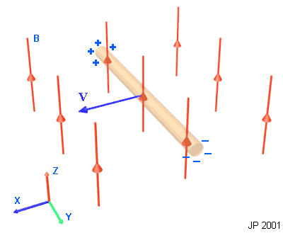
The direction of the force is always at right angles to the flux and the current direction. When using the simplified equation, the direction of the force is given by the right hand rule. 12. Induced Voltage, Faraday's Law and Lenz's Law One last thing we need to consider is induced voltage. This is just an extension of the analysis of the force on a charged particle. If we take a conductor (something with mobile charge) and move it at some speed, V, relative to a magnetic field, the free charges will experience a force which will push them to one end of the conductor. In a metal bar there will be a charge seperation where some electrons have been forced to one end of the bar. The diagram below shows the basic idea.
Fig 12.1 Voltage induced across a moving conductive bar
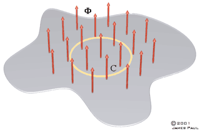
The result of any relative motion between a conductor and a magnetic induction will be an induced voltage generated by charge motion. However, if the conductor moves parallel to the flux (the Z direction in fig X) then no voltage will be induced. We can look at another situation where an open planar surface is penetrated by a magnetic flux. If we set up a closed contour, C, then any change in the flux linking C will induce a voltage around C.
Fig 12.2 Flux bounded by contour
Now if we introduce a conductive loop in place of C then the changing flux will induce a voltage in this conductor driving a current around the loop. The direction of the current can be found by applying Lenz's Law which basically states that the effect acts in opposition to the cause. In this case the induced voltage will drive a current which opposes the change in flux - if the flux decreases then the current will try and maintain the flux (anticlockwise current), if the flux is increasing then the current will try and oppose the increase (clockwise current). Faraday's Law states the relationship between induced voltage, changing flux and time -
The negative symbol is a consequence of including Lenz's Law.
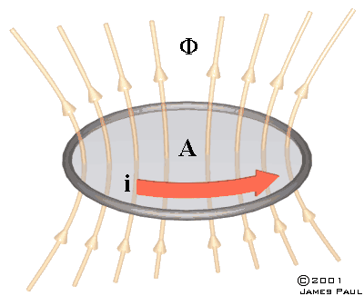
13. Inductance Inductance can be described as the ratio of flux linkage to the current producing the flux. For example, consider a wire loop of cross-sectional area, A, carrying a current I.
Fig 13.1
The self inductance can be defined as
If the loop is composed of more than one turn then the expression becomes
where N is the number of turns. It's important to realise that the inductance is only a constant if the loop has an 'air core', ie is surrounded by air. When a ferromagnetic material is part of the magnetic 'circuit' it introduces a non-linear behaviour into the system which results in a variable self inductance. |


