|
Enhanced Flux Linkage Experiments
Enhancing the Flux Linkage - The reason for enhancing the flux linkage is that it improves efficiency by increasing the force and therefore work done on the projectile for a given coil current. In order to increase the flux linkage we need to increase the permeability of the path along which the flux 'flows'. This is done by introducing a ferromagnetic material such as iron or electrical steel into the air space around the coil. Fig 1a shows the three configurations that are compared in these experiments. Fig 1b and 1c show the results of magnetostatic FEMM simulations in which the coil current is fixed and 1006 carbon steel is introduced into the flux path. The current density used to generate the results of fig 1c is twice that of 1b. The projectile is a mild-steel right-cylinder with a length of 25 mm and a diameter of 9.4 mm. The coil dimensions were set as outlined in table 1.
Fig 1a. Addition of flux path enhancement.
Fig 1b. Force curves for flux enhancement configurations.
Fig 1c. Force curves for flux enhancement configurations.
Table 1. Coil parameters.
Clearly the addition of flux path enhancement causes a large increase in the peak force, accompanied by a flattening of the force curve. It is interesting to note the proportional reduction in force enhancement when the current density is increased. This can be attributed to the reduced permeability as the shell material gets closer to saturation. Two other noteworthy features of these curves are: firstly, the plain coil force exceeds that of the flux-enhanced versions as delta becomes negative; and secondly, the gradient of the force curve is much steeper at the midpoint for flux-enhanced coils. The first point suggests that velocity will be more sensitive to negative values of launch delta with flux-enhanced coils. The second feature points to the likelihood of increased turn off sensitivity with the flux enhanced coilguns since suckback may become more dominant. The shell needs to be formed from either a laminated or powdered material so as to minimise eddy currents and thus allow rapid diffusion of the field into the shell. A laminated structure formed from mains transformer leaves has been investigated by Barry(1). It was decided that a simple comparative investigation between a plain coil and a powdered-iron flux-enhanced coil should be undertaken. The use of powdered iron allows for the construction of a shell of any desired shape, within the limits of basic moulding and machining processes.
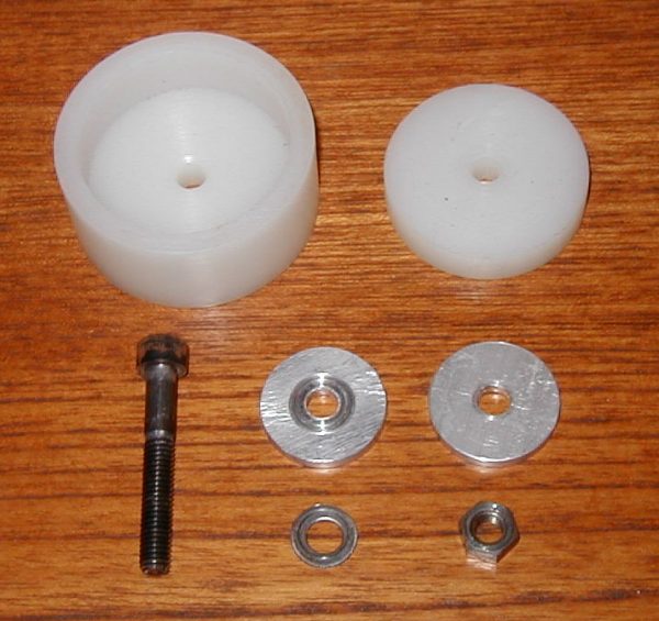
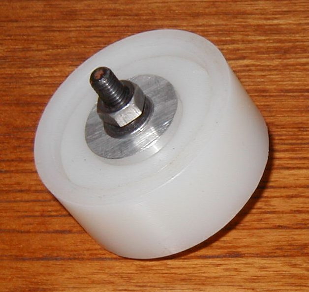
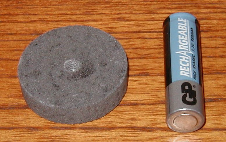
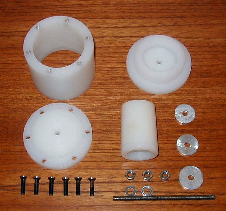
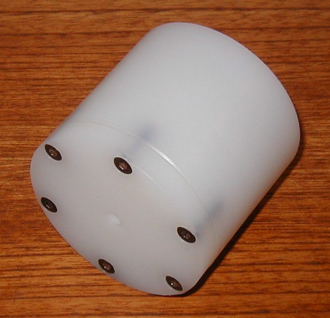
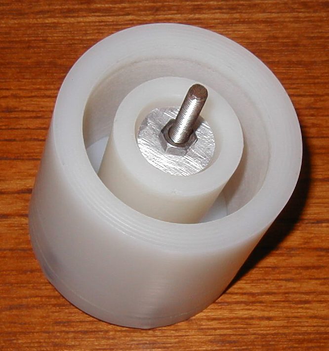
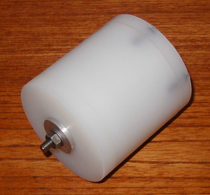
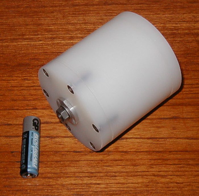
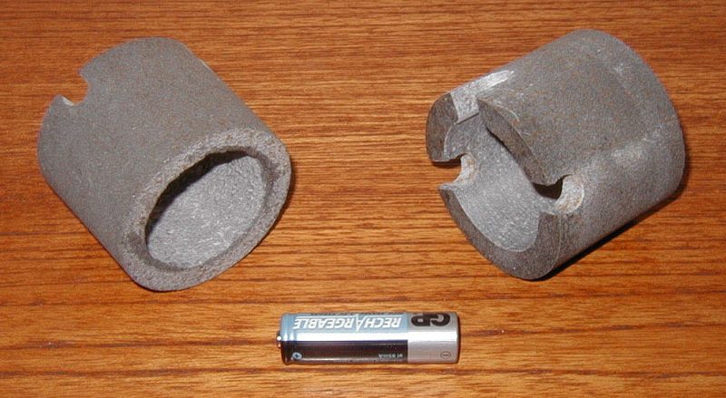
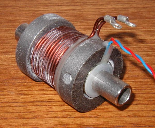
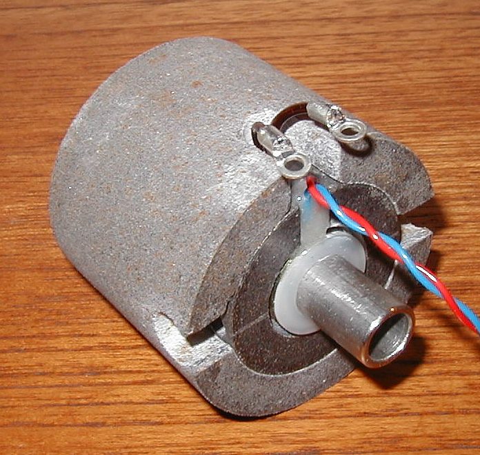
Making The Shell - The shell was designed as three distinct parts; two end pieces and a sleeve. The sleeve fits over the end pieces forming the complete shell. The shell material is a mixture of potting epoxy and iron powder with a maximum particle size of 450 um. The moulds for the end pieces and sleeve are made from nylon 66. The moulds, moulded parts, and completed flux enhanced coilgun are shown in figs 2a - 2k (click for larger image). The mould mixture was prepared by adding epoxy to a quantity of iron powder until the mixture had the consistency of a moist paste. The mixture was then introduced into the mould in small quantities and lightly packed with the end of a dowel. When the mould was filled to the desired level the lid was fitted and the compression nut tightened as much as possible. Due to the limited compression forces that can be applied in a nylon mould the resulting percentage of iron in the epoxy matrix was only about 60 % by mass. The mixture was allowed to cure for a period of 48 hrs before removing the parts. The bore of each end piece was turned to the diameter of the stainless steel tube, with one of the end pieces modified to accept both optical and induced voltage sensors (latter not used in these experiments), and then epoxied in place. After an appropriate curing period the assembly was turned in the lathe to produce an accurate diameter on the end pieces. The bore diameter of the shell was turned to produce a snug fit over the end pieces and cutouts were formed to allow access for the coil wiring and optical sensors. No attempt has been made to characterise the magnetic properties of this material as this will be investigated when a more effective moulding system is developed.
Experiment - Three coilgun configurations were tested; a plain coil, a coil with iron powder end pieces, and a coil with a full iron-powder shell. The triggering system was an optical gate combined with a delta-peak trigger to allow for variation in the launch delta. The switch comprised a set of 8 IRF3415 MOSFETs connected in parallel and an MC34152 MOSFET driver. A series connection of ten 1N5402 rectifier diodes were used to ramp down the coil current at turn off. No resistive current sensor was employed during these experiments as this is slightly detrimental to efficiency. Six sets of experimental runs were conducted as outlined in table 2. Two speed trap values were taken for each launch delta. The remaining voltage on the capacitor was also recorded.
Table 2.
(1) Coilgun Mark III Last Modified: 30 Mar 2004 |
|