|
Launch
Position
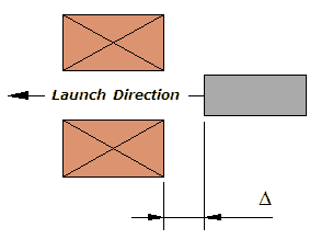
This set of experiments looks at how the launch start position affects the muzzle velocity and corresponding efficiency. Firstly
let us define the 'launch position
Fig 1. The
energy source used in these experiments comprises several different
capacitors as detailed in table 1. Note that the third capacitor
in these experiments consists of two of the 6,800 uF capacitors
connected in parallel. The coil employed throughout the tests is
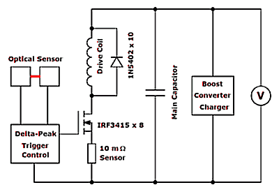
detailed in table 2. The test setup is shown diagrammatically in
fig 2. The delta-peak
trigger uses the optical sensor to control the turn off point
while allowing the launch position to be varied. The
power MOSFET module consists of eight IRF3415 devices connected
in parallel giving a pulsed current capability of around 800 A (based
on a half-sine pulse of ~4 ms). These are switched via an MC34152
MOSFET driver. A 10 m
Fig 2. General test setup.
It should be noted that the positioning of the current sensor causes a reduction in the MOSFET G-S voltage proportional to the sensor current (10_mV/A). The nominal G-S drive voltage is therefore set high enough such that the minimum G-S voltage is at least 10 V. The MC34152 can be operated with supply voltages up to 18 V. The sensor current isn't a parameter of particular interest, but the current traces do provide information on the pulse width. The reason for placing the current sensor in this location is that 'accidents' are less likely when the measuring equipement is connected to the system ground potential. The current sensor also reduces the maxumum possible efficiency since it comprises a significant fraction of the overall circuit resistance.
Table 1. Capacitors used in tests.
Table 2. Coil Parameters.
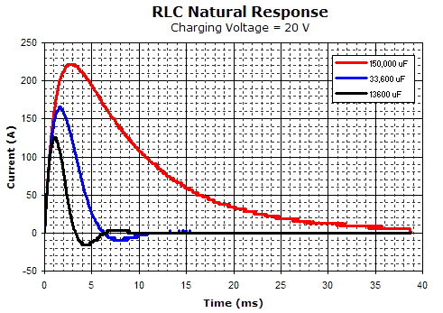
The natural response of the system for each capacitor is shown in fig 3.
Fig 3. RLC behaviour with different capacitors.
Results:
Last Modified: 13 Feb 2004 |
|


